Detection system suitable for identifying and tracking buried pipes or other bodies buried in the ground or embedded in civil engineering works

a technology of detection system and buried pipe, which is applied in the direction of mechanical equipment, instruments, and mechanical devices using reradiation, etc., can solve the problems of high installation cost, system is unsuitable for the practical problem, and the detection of unloaded powered cables is not possibl

Inactive Publication Date: 2010-05-06
SOC PLYMOUTH FR +1
View PDF8 Cites 63 Cited by
  • Summary
  • Abstract
  • Description
  • Claims
  • Application Information

AI Technical Summary

Benefits of technology

[0050]The shape and the size of the elements allow densification of the in...

Problems solved by technology

However, the cost and complexity of the systems implemented mean that these systems are unsuitable for the practical problems posed.
Such a solution has the drawback of needing to partially access the pipe or the associated metal element in order to inject the electrical signal, via units installed at regular distances on the line serving as access points.
However, the detection of an unloaded powered cable is not possible since only a flowing current generates a magnetic field.
The drawback of such a system resides in the fact that, in order to track a pipe, markers need to be buried at regular intervals that are sufficiently close together so as not to lose the pipe, ...

Method used


Image

  • Detection system suitable for identifying and tracking buried pipes or other bodies buried in the ground or embedded in civil engineering works
  • Detection system suitable for identifying and tracking buried pipes or other bodies buried in the ground or embedded in civil engineering works
  • Detection system suitable for identifying and tracking buried pipes or other bodies buried in the ground or embedded in civil engineering works

Examples


first embodiment

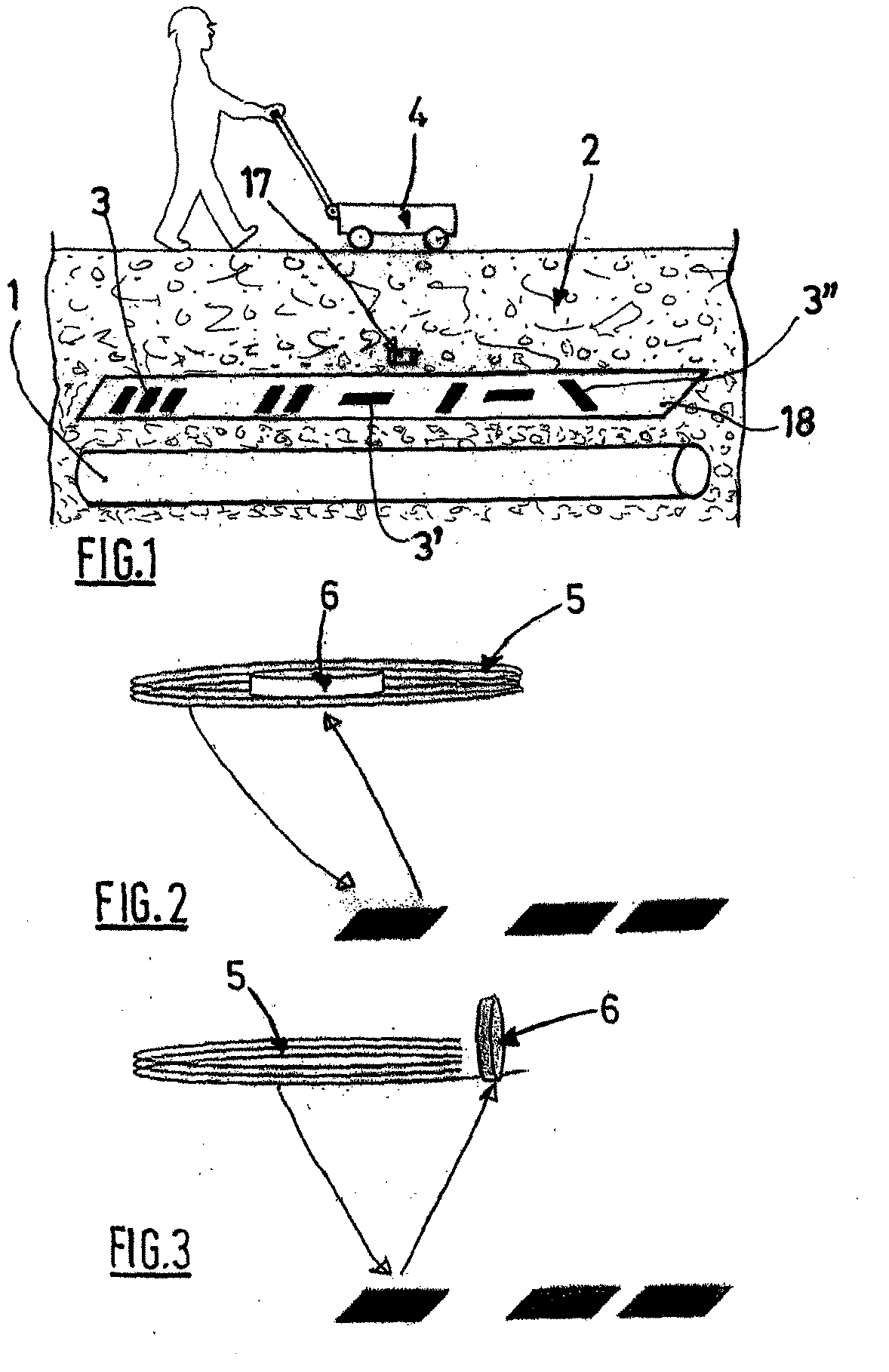
[0061] shown in FIG. 2, each receiving coil 6 is disposed parallel to the corresponding transmission coil 5 and within the shadow region of the latter, in other words substantially in the center of the latter.

second embodiment

[0062] shown in FIG. 3, the receiving coil 6 is disposed perpendicularly to the transmission coil 5 and to the axis of the pipe 1.

[0063]There could also be several receiving coils 6 associated with each transmission coil 5.

third embodiment

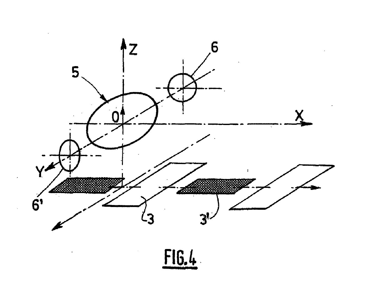
[0064] shown in FIG. 4, the system comprises at least one transmission coil 5 disposed in parallel with the coding elements 3, in other words in the XOY plane, and associated with at least two receiving coils 6 and 6′, disposed for example on either side of the transmission coil, the receiving coil 6 being disposed in the plane parallel to the XOZ plane and the coil 6′ being disposed in a plane parallel to the YOZ plane.

[0065]The combination of the receiving coil 5 and the receiving coil or receiving coils 6 then forms an electromagnetic detector based on the principle of induction balance.

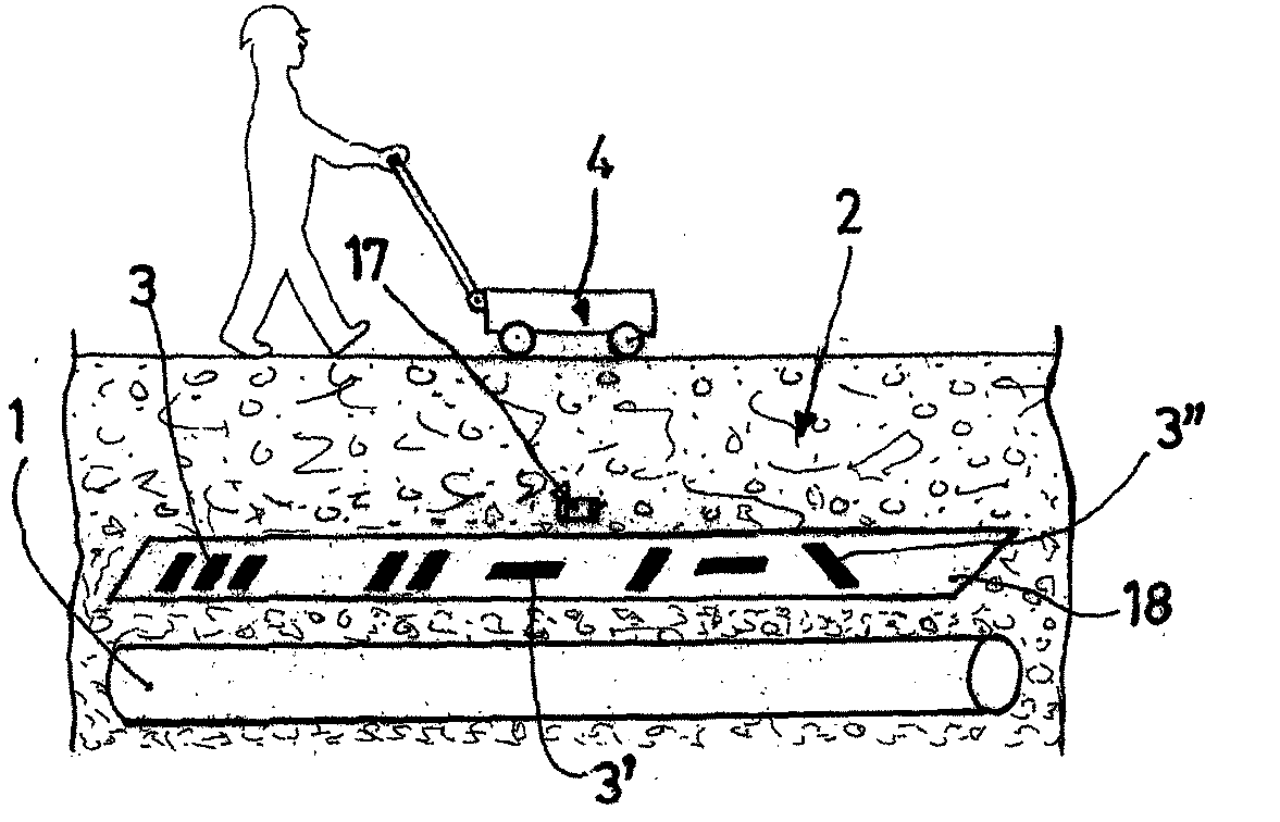
[0066]The invention aims to use the magnetic properties of the coding elements 3, 3′ and 3″.

[0067]For this purpose, an electromagnetic wave of given frequency and energy is sent into the ground 2, in the direction of the pipe 1, in order to reach the coding elements 3.

[0068]The ground comprises a plurality of extraneous elements 17, generally composed of conducting materials and / or magnetic materi...


PUM


Abstract

The invention relates to a detection system suitable for identifying and tracking buried pipes or other bodies buried the ground or embedded in civil engineering works, which comprises: a coding device affixed to or integrated into the objects (1), taking the form of a succession of thin coding elements (3), each forming a surface of predetermined size, these elements being separated from one another, and their arrangement making it possible to define a code; and a detection device comprising at least one transmission coil (5), at least one reception coil (6) and a signal processing device for processing the signals coming from the various coils (5, 6), characterized in that at least some of the coding elements (3) are made of magnetic material, the detection device being designed to saturate or modify the point of operation of the coding elements (3) in their operating cycle, which then emit a frequency-rich signal made up of a wave having the fundamental frequency and waves having a frequency that is a multiple of the fundamental frequency, called harmonics, to gather and process the signal coming from these elements (3) and to reconstruct the coding of the object (1).

Description

BACKGROUND OF THE INVENTION[0001]The invention relates to a detection system suitable for identifying and tracking buried pipes and conduits or other bodies buried in the ground or embedded in civil engineering works.[0002]Civil engineering works are, for example, roads or bridges.[0003]The difficulty in obtaining information on the presence, the layout and the nature of buried pipes, conduits or lines relates to the fact that, most of the time, nothing is visible from the outside and that existing plans often turn out to be inaccurate, incomplete, or even sometimes incorrect.[0004]In order to save time and reduce costs, it is important to be able to detect the presence of such pipes, conduits and lines, and to locate them with precision, without digging up the ground or destroying construction works, when later work is to be carried out. Generally speaking, the methods used must be simple to implement by site personnel with modest qualifications. Furthermore, the equipment used to ...

Claims


Application Information

Patent Timeline
IPC IPC(8): G01V3/08
CPCG01V15/00F16L1/11
Inventor ARNAUD, DANIELBELLOIR, FABIANDAMOUR, FRANCOIS-XAVIERREYAL, JEAN-PIERRE
Owner SOC PLYMOUTH FR
Why Eureka
Try Eureka