Collision resolution protocol for mobile RFID tag identifiaction

a technology of collision resolution and mobile rfid, which is applied in the field of radio frequency identification (rfid), can solve problems such as difficult selection of bin slots, tag collision problems, and inability to avoid collisions during communication between a reader and multiple tags, and achieve the effect of improving the identification process of tags

Active Publication Date: 2010-05-06
AT&T INTPROP I L P +1
View PDF1 Cites 26 Cited by
  • Summary
  • Abstract
  • Description
  • Claims
  • Application Information

AI Technical Summary

Benefits of technology

[0008]In according with the principles of the present invention, and in a departure from the prior art, we have recognized that the tag identification process ...

Problems solved by technology

One of the most challenging issues in RFID systems is the tag collision problem.
When only one RF channel is used, as is typically the case in passive RFID systems, it is impossible to avoid collisions during communication between a reader and multiple tags.
However, selection of the appropriate number of bin slots is a challenging problem.
As the number of bin slots gets smaller relative to the tag population, the collision-spreading effect of this approach becomes le...

Method used


Image

  • Collision resolution protocol for mobile RFID tag identifiaction
  • Collision resolution protocol for mobile RFID tag identifiaction
  • Collision resolution protocol for mobile RFID tag identifiaction

Examples


Embodiment Construction

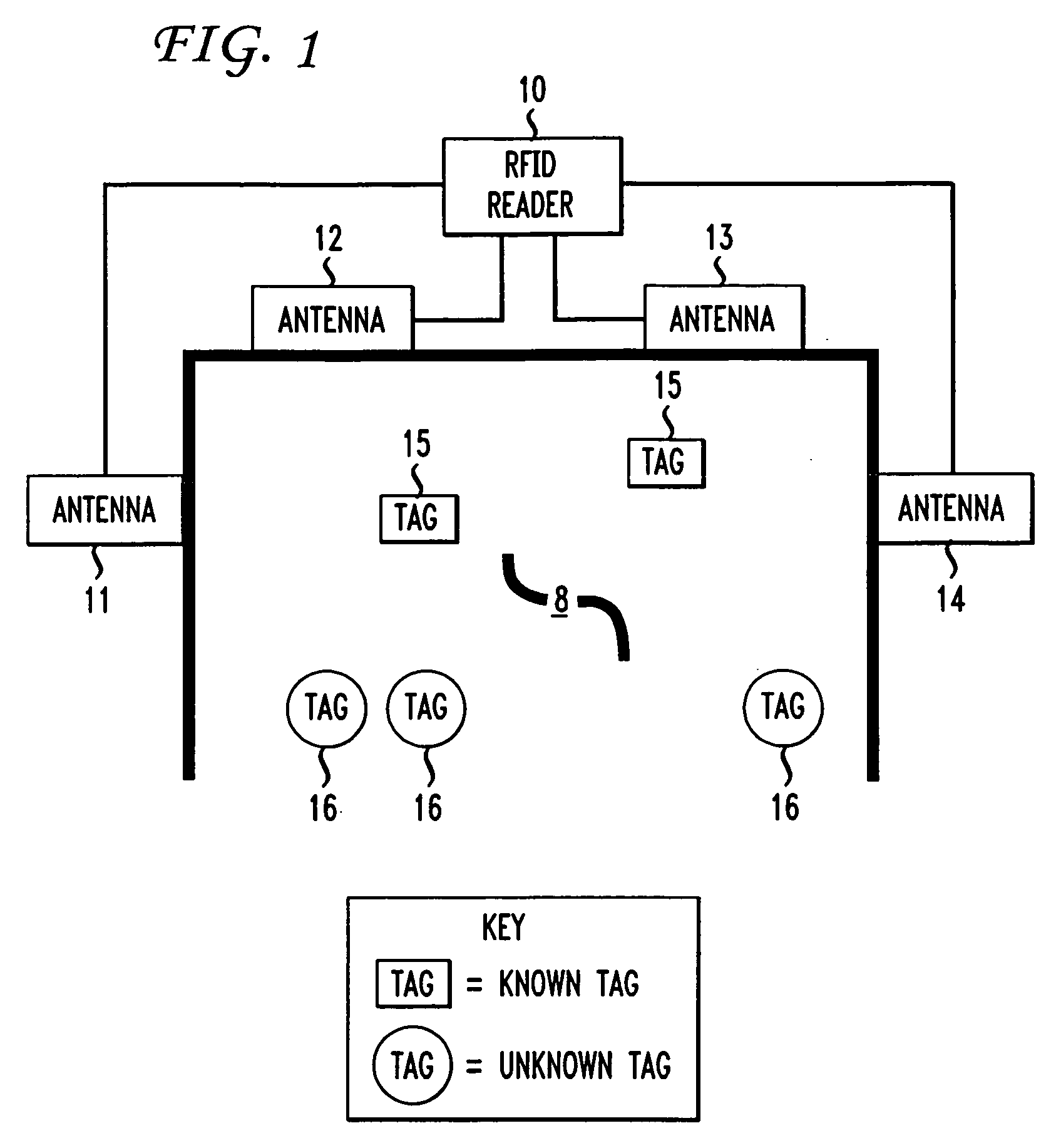
[0015]FIG. 1 shows a radio frequency identification, or RFID, system in which the present invention is illustratively implemented. RFID reader 10 uses multiple antennas 11, 12, 13 and 14 to detect signals from RFID tags 15 and 16 within an area 8, such as the area in the vicinity of a loading dock. Area 8 is hereinafter referred to as the reader's interrogation zone—this being a zone within which signals generated by the tags are detectable by the reader. The invention is equally applicable to environments in which there are multiple readers and tags traverse multiple interrogation zones. In warehouse environments, for example, the locations of items are tracked through an array of RFID readers.

[0016]Tags 15 are assumed to have been in interrogation zone 8 for some period of time in the past and have already been identified by reader 10 as being in interrogation zone 8. These are referred to herein as “known tags.” Tags 16 are assumed to have entered interrogation zone 8 since the l...


PUM


Abstract

The performance of a radio frequency identification (RFID) system is improved by a protocol that eliminates collisions between signals generated by a) RFID tags that the RFID reader has already identified as being in its interrogation zone and b) RFID tags that are newly arrived and thus that the reader has not yet identified. This is illustratively accomplished by the use of separate identification and access frames. It is during the identification frame that newly arrived tags become identified by the reader. Although there may be collisions during the identification frame, those collisions are only among newly arrived tags. The already-identified tags communicate with the reader during respective time slots of the access frame, so that they neither collide with each other nor with the newly arrived tags.

Description

BACKGROUND[0001]The present invention relates to radio frequency identification (RFID).[0002]Radio frequency identification (RFID) is a method to retrieve and store data using a radio channel. A RFID system consists of tags and a reader. A tag typically consists of radio-frequency circuits, a CPU, and a small memory and has a unique identifier, or “TAG_ID.” By means of wireless communication between a reader and tags in which the tags identify themselves by communicating their respective identifiers to the reader, RFID systems track and / or manage objects in real-time.[0003]One of the most challenging issues in RFID systems is the tag collision problem. When only one RF channel is used, as is typically the case in passive RFID systems, it is impossible to avoid collisions during communication between a reader and multiple tags. Passive tags only listen and respond to requests from the reader and do not interact with one another.[0004]Several collision resolution protocols have been p...

Claims


Application Information

Patent Timeline
IPC IPC(8): H04Q5/22
CPCG06K7/0008G06K7/10019H04Q2213/13003H04W74/0841
Inventor NOEL, ERICTANG, KITMING WENDYYU, JAEWOOK
Owner AT&T INTPROP I L P
Why Eureka
Try Eureka