Mobile Surveillance System

a camera system and mobile technology, applied in the field of surveillance camera systems, can solve the problems of limited application of pan and tilt camera systems to moving vehicles, unsuitable for external use, and the ‘handy cam-corder’ mounted inside the vehicle does not enable the best field of view, so as to achieve easy and safe operation and easy and safe operation

Inactive Publication Date: 2010-05-06
JOHNSTON GREGORY E +1
View PDF8 Cites 100 Cited by
  • Summary
  • Abstract
  • Description
  • Claims
  • Application Information

AI Technical Summary

Benefits of technology

[0019]Another object of the invention is said mobile display-control has six degree of freedom mounting system for best individual viewing angle adjustment and can be operated with a single hand for easy and safe operation in a moving vehicle.
[0020]A further object of the invention is said mobile display-control incorporates control of pan and tilt, zoom, focus, autofocus, stabilization, and display brightness and can be operated with a single hand for easy and safe operation in a moving vehicle.

Problems solved by technology

From the introduction of the wheel, applying a pan and tilt camera system to moving vehicles has been limited.
‘Handy cam-corder’ mounted inside vehicle does not enable best field of regard (FOR) nor is it ruggedized for external vehicle mounting above the roof and outboard the vehicle's side.
No pan and tilt mechanism and not applicable to mobile vehicle environment nor for patrol guard image capture.

Method used


Image

  • Mobile Surveillance System
  • Mobile Surveillance System
  • Mobile Surveillance System

Examples


Embodiment Construction

[0045]Detailed descriptions of the preferred embodiment are provided herein. It is to be understood, however, that the present invention may be embodied in various forms. Therefore, specific details disclosed herein are not to be interpreted as limiting, but rather as a basis for the claims and as a representative basis for teaching one skilled in the art to employ the present invention in virtually any appropriately detailed system, structure or manner.

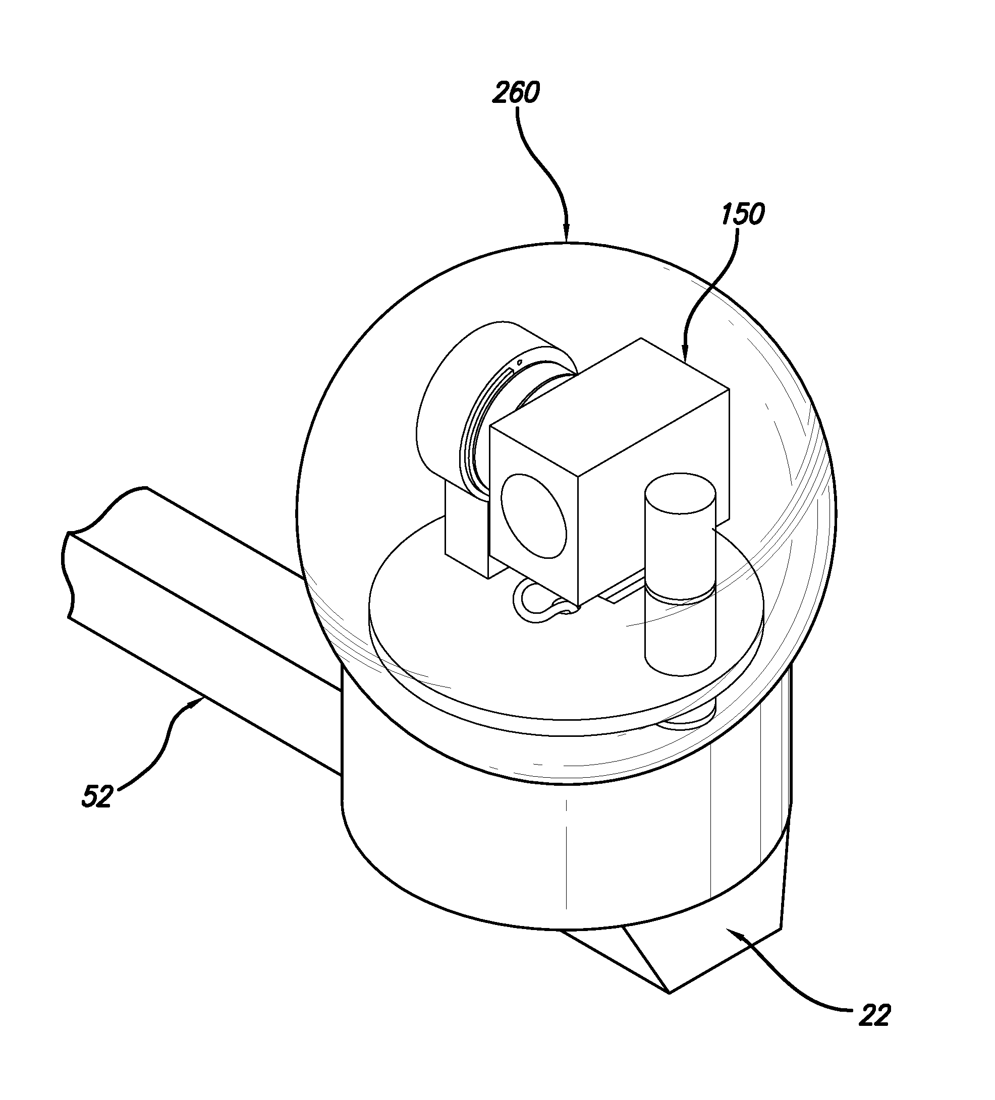
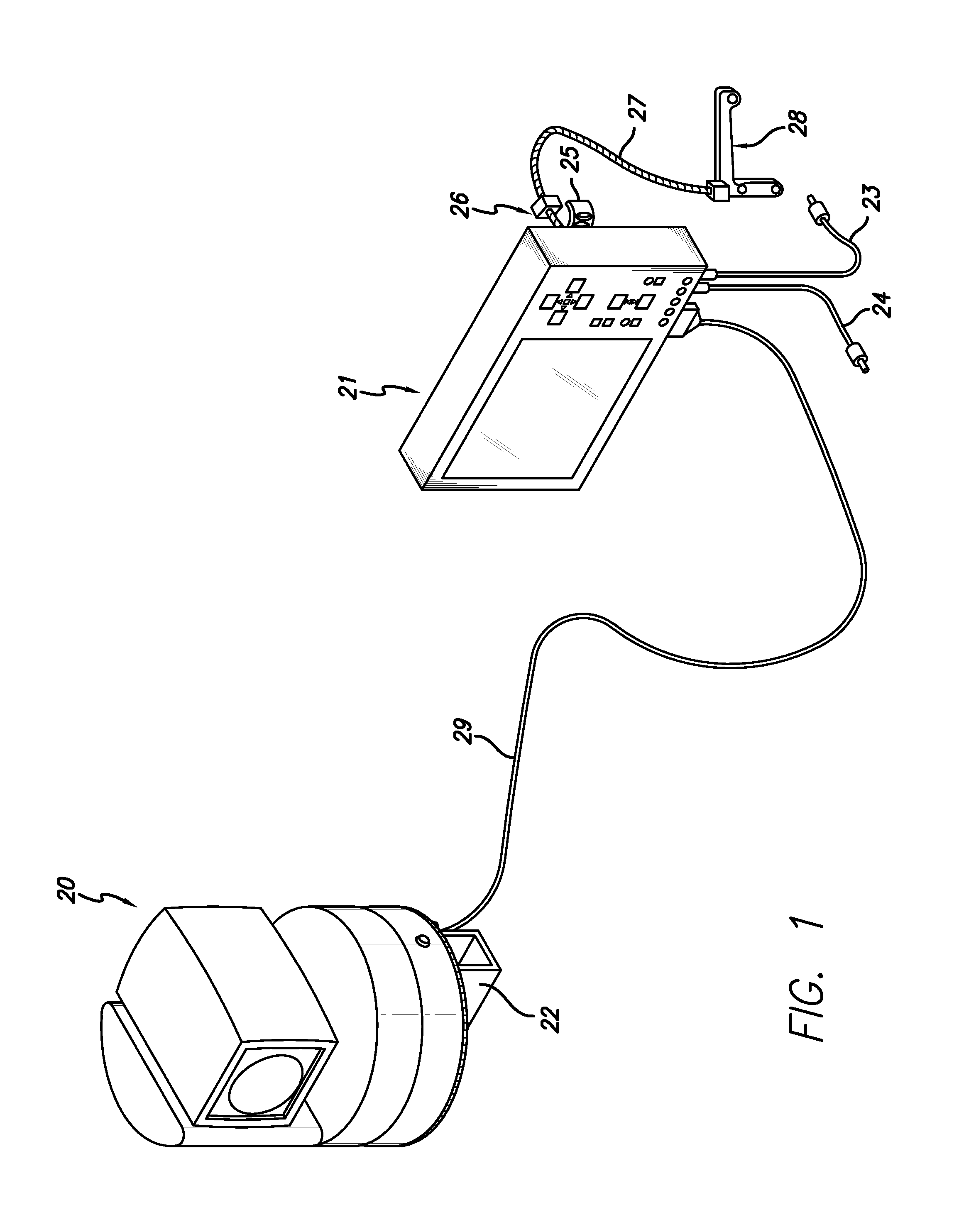
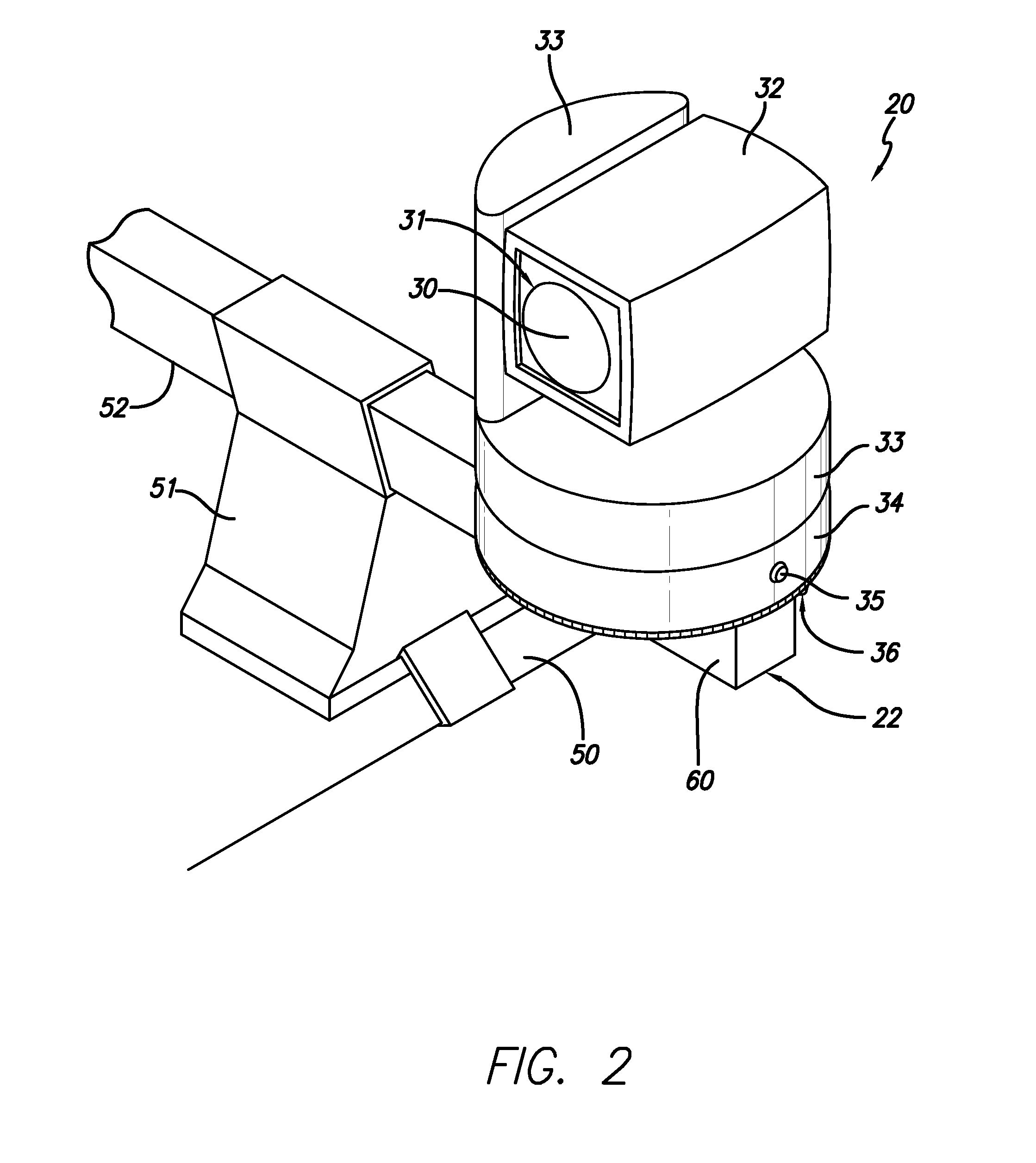
[0046]FIG. 1 shows a mobile pan and tilt camera (20) that is attached to an electro-mechanical mount (mounting assembly) (22) and is interconnected electrically by a cable (29) to a display-control apparatus (21). Said display-control (21) is attached to an adjustable yoke (26) such that with a single hand, one can adjust the viewing angle of said display-control (21) by moving a yoke lever (25) from a lock position to an unlock position and back to said lock position. Said adjustable yoke (26) is attached to a goose neck (27) where ...


PUM


Abstract

A mobile pan and tilt camera and display-control apparatus comprising a fully rotatable camera mounted to a vehicle for capturing images, a display-control box having an image display screen and control buttons for controlling said camera and its movement attached to an adjustable mount in said vehicle within an operator's view and reach, an image capture box for storage on various recording media or for transmission of said captured mobile images, said captured mobile images are sent by radio frequency transmission to a data storage server for a consumer to access. A preferred embodiment includes further comprising a mount that incorporates a quick disconnect mechanism along with a locking mechanical base and an electronic signal connector for easy camera installation and removal. A preferred embodiment includes further comprising a double locking mechanism where one mechanism is a security fastener.

Description

[0001]This application is a continuation of prior application Ser. No. 09 / 059,077, filed Apr. 9, 1998BACKGROUND OF THE INVENTION[0002]This invention relates generally to the field of surveillance camera systems, and more particularly to an apparatus and process for capturing images by mobile security guards.[0003]Pan and tilt mechanisms for pointing cameras are old as dirt. From the introduction of the wheel, applying a pan and tilt camera system to moving vehicles has been limited. The operation of moving vehicles has evolved and now the opportunity for the addition of augmented vision can be utilized by the vehicle operator for various applications like mobile patrol guard image acquisition or improved driver safety. This technology started in August of 1977 with the incorporation of a cathode-ray tube and video camera on a tripod between the seats of an automobile. Tests were conducted and videotapes were produced through 1980. The project was rekindled in 1996 by using a traditi...

Claims


Application Information

Patent Timeline
Patent Type & Authority Applications(United States)
IPC IPC(8): H04N7/18H04N5/222H04N5/225
CPCH04N5/2251H04N5/23203H04N5/23293H04N7/185H04N23/50H04N23/66H04N23/63H04N23/695
Inventor JOHNSTON, GREGORY E.LEVINKRON, ARIE
Owner JOHNSTON GREGORY E
Why Eureka
Try Eureka