
Display system, image output device and image display device

a display system and image output technology, applied in the field of display system, image output device and image display device, can solve the problems of user switching modes, deterioration of non-natural images, and high device cos

Active Publication Date: 2010-05-06
SEIKO EPSON CORP
View PDF9 Cites 20 Cited by
  • Summary
  • Abstract
  • Description
  • Claims
  • Application Information

AI Technical Summary

Benefits of technology

[0010]An advantage of some aspects of the invention is that a display system, an image output device and an image display device can be provided that can be configured inexpensively and can output images corresponding to image types.

Problems solved by technology

However, deterioration of non-natural images tends to be conspicuous since these images have many areas containing straight lines.
However, the digital camera described in JP-A-2001-218065 has a problem that the user needs to switch modes between pickup of a natural image and pickup of a non-natural image.
Therefore, the device has a problem that a storage unit to save the immediately previous picked-up image that is immediately before (an image of at least one frame) is needed for the comparison between the images and this makes the device expensive.
That is, a natural image has relatively few areas containing straight lines and has a relatively unnoticeable edge.
Therefore, if a compressed image data with a high compression rate is generated from the natural image, deterioration in image quality tends to be unnoticeable and the data volume of the compressed image can be substantially reduced.

Method used


Image

  • Display system, image output device and image display device
  • Display system, image output device and image display device
  • Display system, image output device and image display device

Examples


first embodiment

1. First Embodiment

[0036]Hereinafter, a first embodiment of the invention will be described with reference to the drawings.

Configuration of Display System

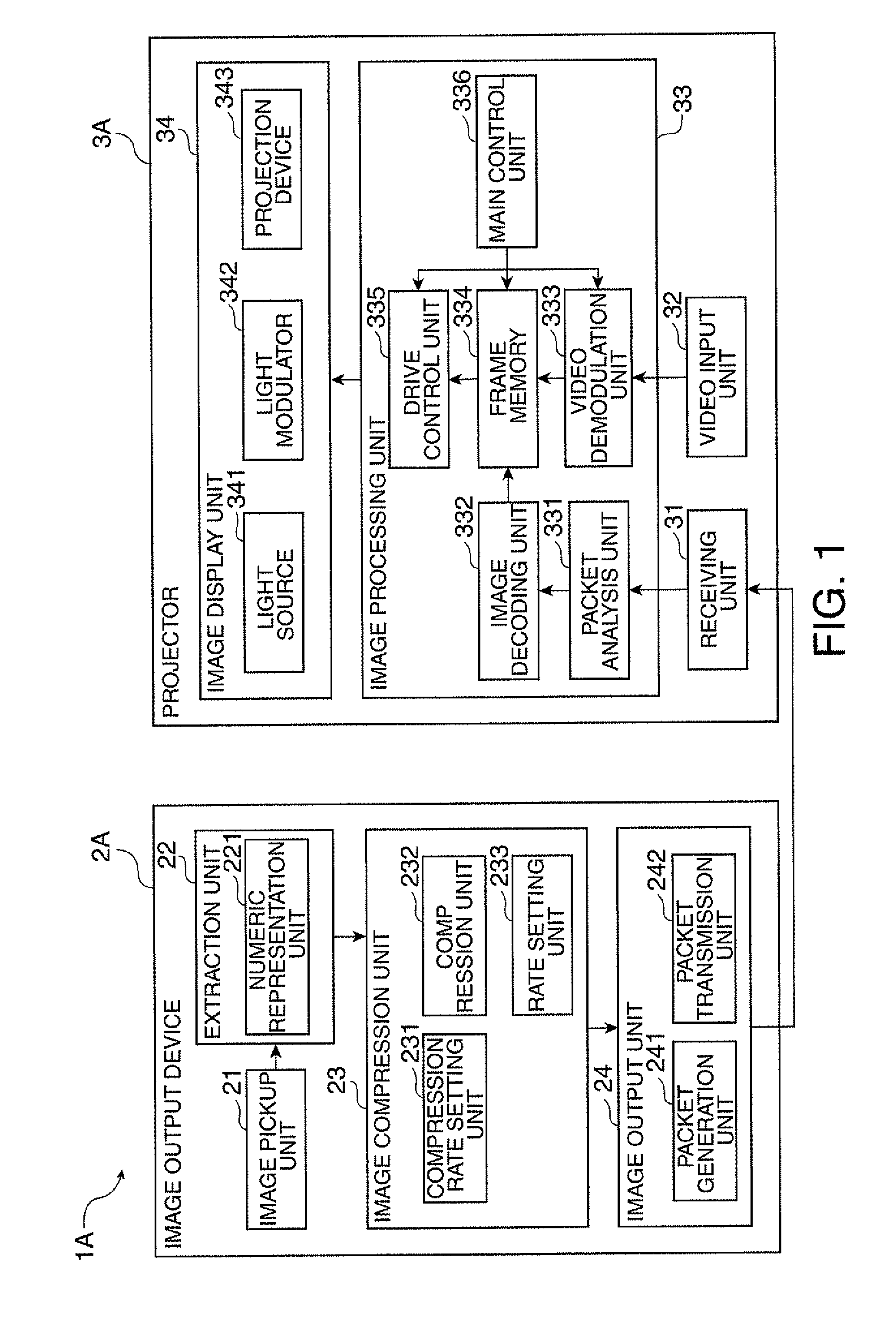
[0037]FIG. 1 is a block diagram showing the configuration of a display system 1A according to this embodiment.

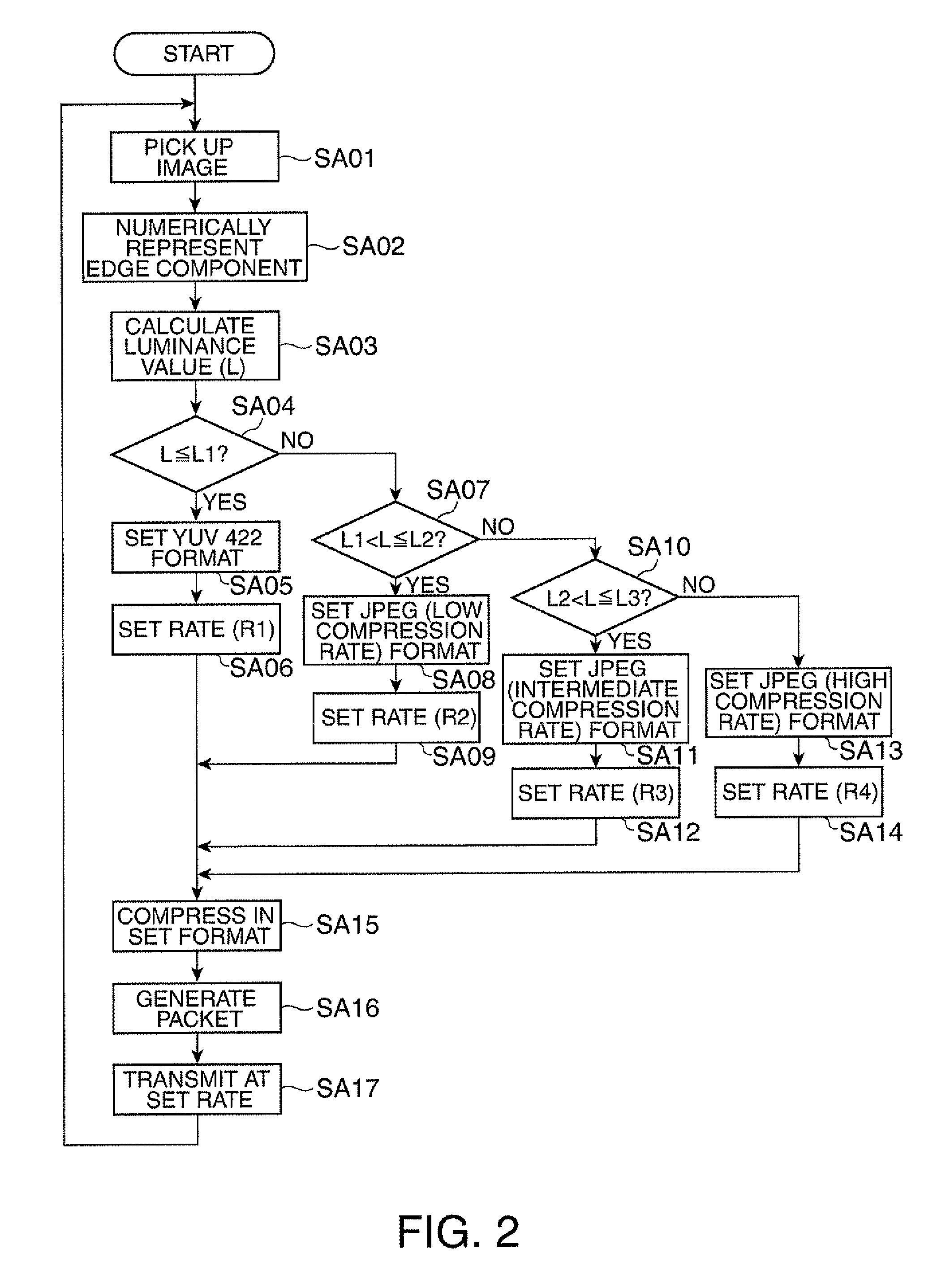
[0038]The display system 1A includes an image output device 2A having the functions of an image pickup device, an image data output device and a control device according to the embodiment of the invention, and a projector 3A as an image display device, as shown in FIG. 1. An image corresponding to image data outputted from the image output device 2A is formed and projected on a projection surface of a screen or the like, not shown, by the projector 3A. In this display system 1A, as an edge component of a picked-up image picked up by the image output device 2A is extracted, it is determined whether the picked-up image is a natural image or a non-natural image. A compression rate for the picked-up image is set in accordance w...

second embodiment

2. Second Embodiment

[0094]Next, a display system 1B according to a second embodiment of the invention will be described.

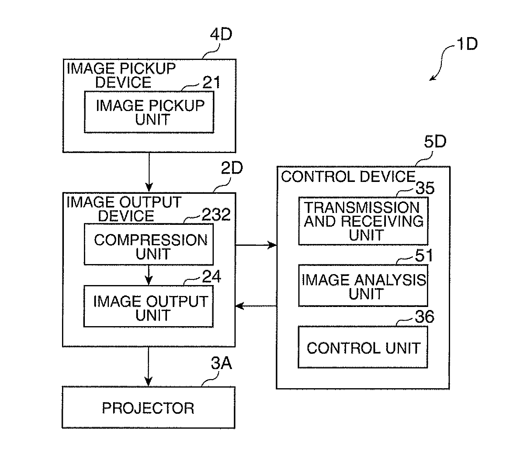
[0095]The display system 1B according to this embodiment has an image output device and a projector, similarly to the display system 1A. However, the display system 1B and the display system 1A are different in the following feature. That is, in the display system 1A, the luminance value L is calculated from an edge component of a picked-up image and a compression rate corresponding to the luminance value L is set, whereas in the display system 1B, a vertical and horizontal component from the edge component is highlighted and then binarized and a compression rate is set in accordance with the number of pixels having high luminance. In the following description, the same parts or substantially the same parts as already described parts are noted by the same reference numerals and will not be described further in detail.

Configuration of Display System

[0096]FIG. 3 is a...

third embodiment

3. Third Embodiment

[0118]Next, a display system 10 according to a third embodiment of the invention will be described.

[0119]The display system 10 according to this embodiment has an image output device and a projector, similarly to the display systems 1A and 1B. However, the display system 1C is different from the display systems 1A and 1B in that, in the display systems 1A and 1B, the image output devices 2A and 2B have the compression rate setting unit 231 and the rate setting unit 233, whereas in the display system 10, the projector has these units.

Configuration of Display System

[0120]FIG. 5 is a block diagram showing the configuration of the display system 1C.

[0121]The display system 1C includes an image output device 20 having the functions of an image pickup device and an image output device according to the embodiment of the invention, and a projector 3C having the functions of a control device and an image display device according to the embodiment of the invention, as shown...


PUM


Abstract

A display system includes: an image data output device which outputs image data; an image display device which displays an image corresponding to the image data; and a control device which controls the image data output device; wherein one of the control device and the image data output device has a compression rate setting unit which determines whether the image corresponding to the image data is a natural image or not and sets a compression rate for the image in accordance with a type of the image; and the image data output device has an image data output unit which outputs a compressed image data acquired by compressing the image data at the compression rate set by the compression rate setting unit.

Description

[0001]The entire disclosure of Japanese Patent No. 2008-283442 filed Nov. 4, 2008 is expressly incorporated by reference herein.BACKGROUND[0002]1. Technical Field[0003]The present invention relates to a display system, and an image output device and an image display device that are used in the display system.[0004]2. Related Art[0005]Traditionally, an image display device such as a projector which forms and displays an image corresponding to inputted image information is known. In many cases, such an image display device is connected to an image output device such as a PC (personal computer) and thus used as a display system.[0006]Images outputted from the image output device and displayed by the image display device are roughly divided into natural images and non-natural images. Of these, natural images are images of landscapes and so on and are often dynamic images, for example, as shown in movies. Meanwhile, non-natural images are images of letters, graphic patterns and so on and...

Claims


Application Information

Patent Timeline
IPC IPC(8): H04N11/02H04N9/31G09G3/20G09G5/00G09G5/36
CPCH04N19/172H04N19/115H04N19/12H04N19/132H04N19/14
Inventor NOBORI, TATSUHIKO
Owner SEIKO EPSON CORP
Learn More