
Illuminating light communication device

a technology of light communication and communication device, which is applied in the field of communication services, can solve the problems of slower transmission speed, and achieve the effect of reducing the amount of illumination, illuminating light communication, and not reducing the performance of illuminating

Inactive Publication Date: 2010-05-06
NAKAGAWA LAB INC
View PDF3 Cites 104 Cited by
  • Summary
  • Abstract
  • Description
  • Claims
  • Application Information

AI Technical Summary

Benefits of technology

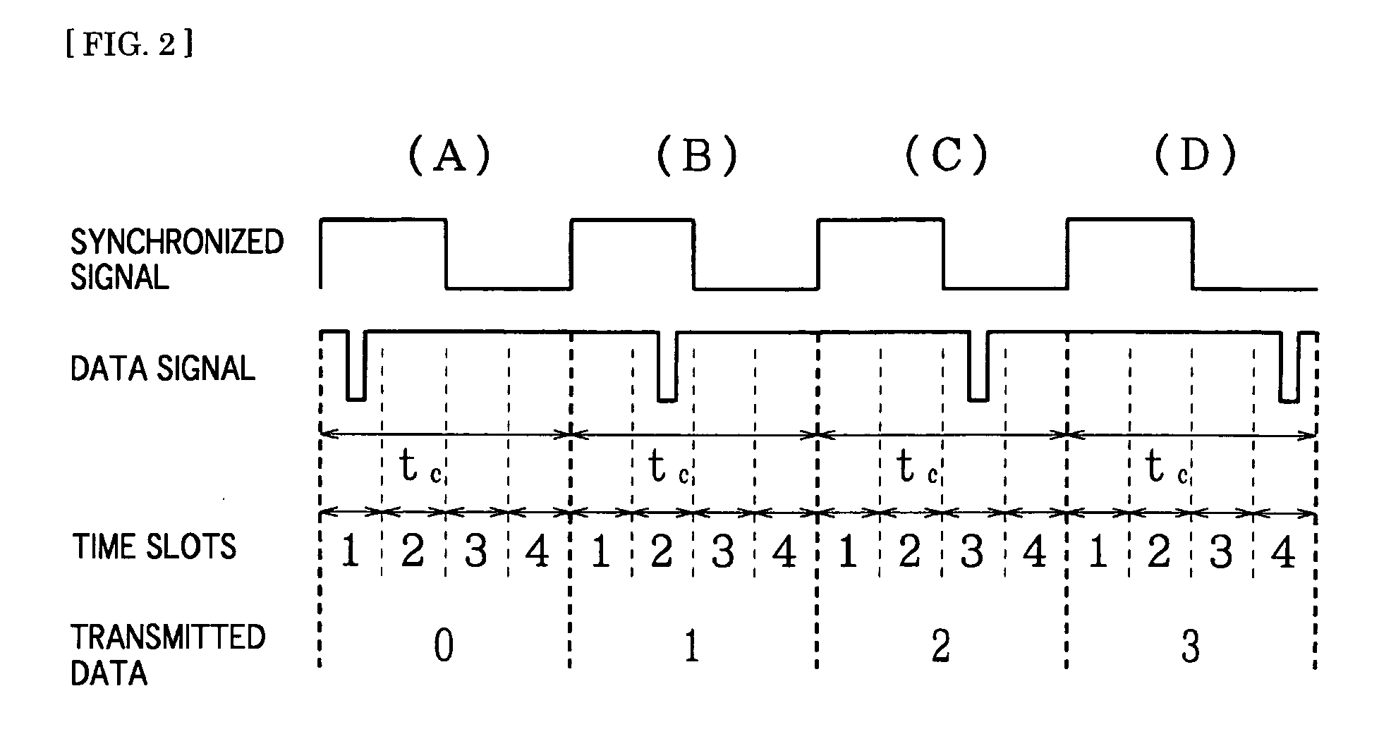
[0011]According to the present invention, by converting the protocol of power-line communication to an optimum protocol for illuminating light communication, illuminating light communication may be carried out without decreasing the performance of illuminating. By using multiple-valued PPM, which defines that existing pulses correspond to OFF while no pulse corresponds to ON, as a modulation system for the protocol of carrying out illuminating light communication, for example, the case of no pulse provides typical illuminating light while case of an existing pulse provides a mere fraction of the time of not lighting. Therefore, communication is possible without much decrease in amount of illumination and with control of fluctuation in amount of light.

Problems solved by technology

However, when using illuminating light for communication, while broadband communication technique may be used for data transmission (downlink) from an illuminating light communication device to each terminal, an infrared data communication technique is typical for data transmission (uplink) from each terminal, and transmission speed is slower than on the uplink.
As such, communication using illuminating light is often carried out at an asymmetrical transmission speed, and there is a problem in this connection in carrying out power-line communication and illuminating light communication using the same protocol.

Method used


Image

  • Illuminating light communication device
  • Illuminating light communication device
  • Illuminating light communication device

Examples


Embodiment Construction

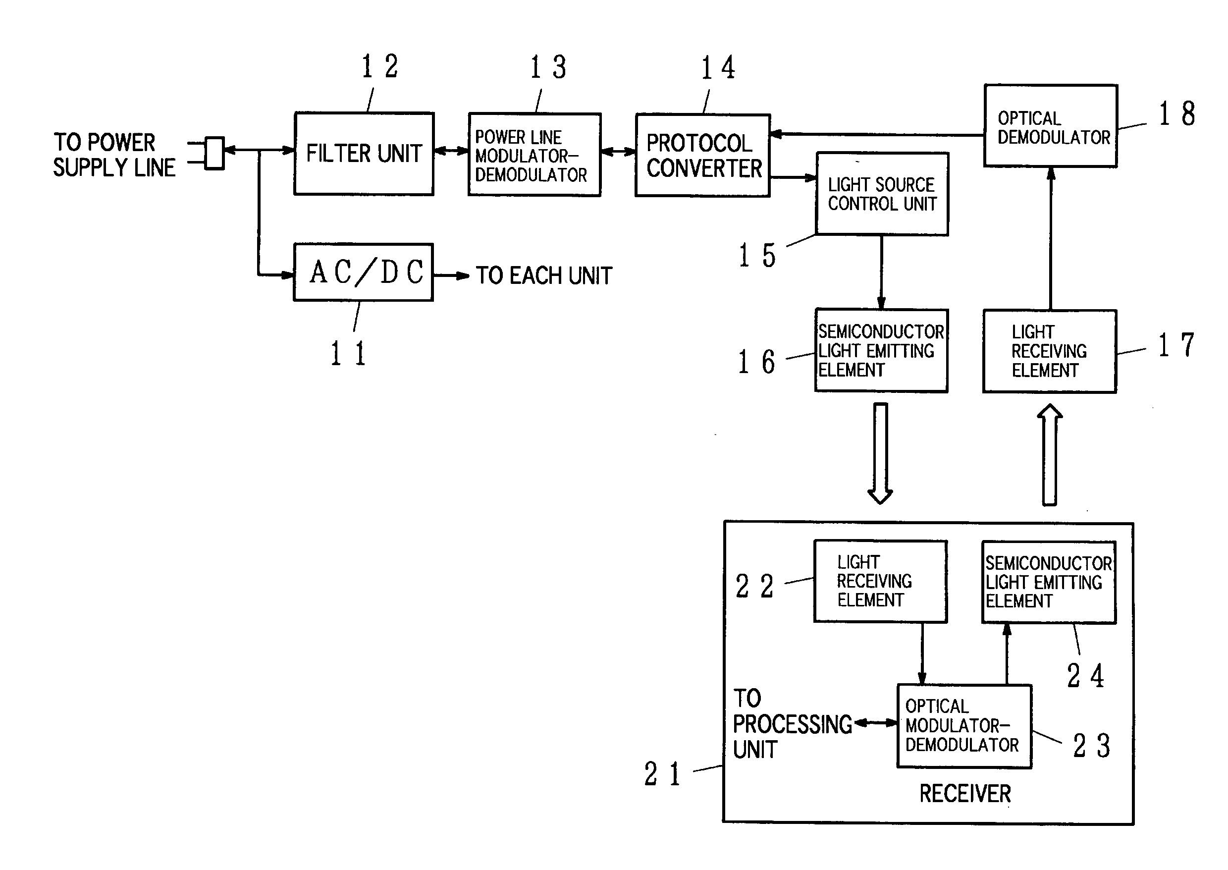
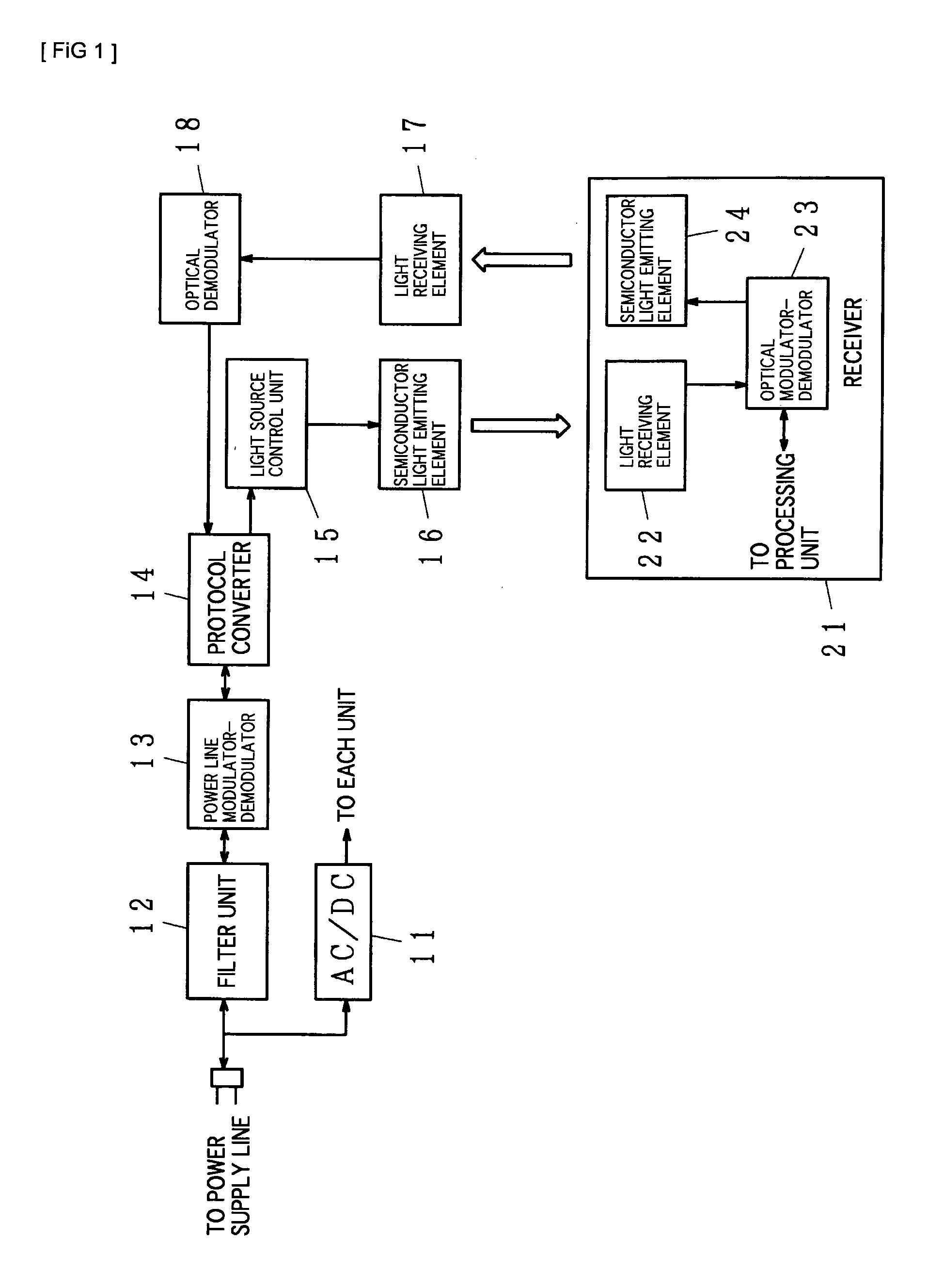
[0015]FIG. 1 is a block diagram showing an exemplary communication system including an embodiment of the present invention. In this drawing, 11 denotes an AC-to-DC converter, 12 denotes a filter unit, 13 denotes a power line modulator-demodulator, 14 denotes a protocol converter, 15 denotes a light source control unit, 16 denotes a semiconductor light emitting element, 17 denotes a light receiving element, 18 denotes an optical demodulator, 21 denotes a receiver, 22 denotes a light receiving element, 23 denotes an optical modulator-demodulator, and 24 denotes a semiconductor light emitting element.

[0016]In the structure given in FIG. 1, the illuminating light communication device of the present invention is constituted by the AC-to-DC converter 11, the filter unit 12, the power line modulator-demodulator 13, the protocol converter 14, the light source control unit 15, the semiconductor light emitting element 16, the light receiving element 17, and the optical demodulator 18. The AC-...


PUM


Abstract

An illuminating light communication device, which is for establishing a communication system capable of controlling fluctuation in intensity of illuminating light when transmitting data using a power line and illuminating light, and satisfactorily carrying out communication using the power line and communication using the illuminating light, is provided. When data is transmitted through the power line, a signal component is extracted by a filter unit 12, and the demodulated by a power line modulator-demodulator 13, thereby retrieving the data. The retrieved data is temporarily stored in a protocol converter 14. Afterward, the data is converted to the optical communication protocol, and blinking or amount of light of a semiconductor light emitting element 16 is controlled according to the data transmitted from a light source control unit 15, thereby modulating the illuminating light. This allows transmission of data utilizing the illuminating light. Multiple-valued PPM, which defines that existing pulses correspond to OFF while no pulse corresponds to ON, may be used as a modulation system for optical communication.

Description

TECHNICAL FIELD[0001]The present invention relates to a communication service of transmitting data using a power line and illuminating light (visible light).BACKGROUND ART[0002]In recent years, semiconductor light emitting elements such as LEDs have been used as a light source for illumination. Controlling blinking or amount of light of the semiconductor light emitting elements at a high speed is possible. Use of this characteristic to control the blinking or amount of light of the semiconductor light emitting elements for illumination according to data has allowed development of technology for transmitting data using illuminating light. If blinking or change in amount of light of a semiconductor light emitting element is fast, that blinking or change in amount of light is undetectable by the human eye. As a result, transmission of data may be performed without impeding use as illuminating light for humans. Moreover, lighting devices are widely and generally used, and there is a mer...

Claims


Application Information

Patent Timeline
IPC IPC(8): H04B10/00H04B3/54H04B10/11H04B10/112H04B10/118
CPCH04B3/54H04B10/1143H04B10/116H04B2203/5408
Inventor ARITA, TAKEMIHARUYAMA, SHINICHIRONAKAGAWA, MASAOYAMAGUCHI, TAKEHIKOKOMINE, TOSHIHIKO
Owner NAKAGAWA LAB INC
Learn More