Cutting arrangement for cutting a workpiece having a tool holder which holds a plurality of cutting tools therein

Inactive Publication Date: 2010-05-06
KENNAMETAL INC
View PDF6 Cites 1 Cited by
  • Summary
  • Abstract
  • Description
  • Claims
  • Application Information

AI Technical Summary

Benefits of technology

[0017]According to one possible embodiment, the locking element is in this case designed as an insert. The locking element is therefore a separate component which is simple to produce and in addition can also be connected to the parent body in a simple and easy-to-fit manner.
[0018]Provision is in one possible embodiment made here for the locking element to be detachably fastened to the parent body. This permits problem-free and simple exchange of the clamping bolt, provided this becomes necessary and/or desired. For example, a clamping connection or a form-fitting connection, for example like a bayonet catch, is provided for the detachable fastening. The locking element is in one possible embodiment screwed to the parent body.
[0019]In addition, according to one possible embodiment, provision is made for the locking element to form a guide for the bolt head. That is to say, at least a section of the bolt head slides in the bolt longitudinal direction inside the locking element. Exact or generally positioning of the clamping bolt and thus a clamping effect of the entire clamping device that is defined as precisely as possible or generally are achieved by this guide.
[0020]In one possible embodiment, provided on the bolt head is a counter-stop, in one possible embodiment in the form of an annular web, which in the fitted

Problems solved by technology

In such a multiple tool holder, however, there is the problem that the tool holder inevitably increases in volume.
This increased space requirement may lead to disadvantages in restricted space conditions.
A through-bore and acce

Method used


Image

  • Cutting arrangement for cutting a workpiece having a tool holder which holds a plurality of cutting tools therein
  • Cutting arrangement for cutting a workpiece having a tool holder which holds a plurality of cutting tools therein
  • Cutting arrangement for cutting a workpiece having a tool holder which holds a plurality of cutting tools therein

Examples


Example

[0035]Parts having the same effect are in each case provided with the same designations in the figures.

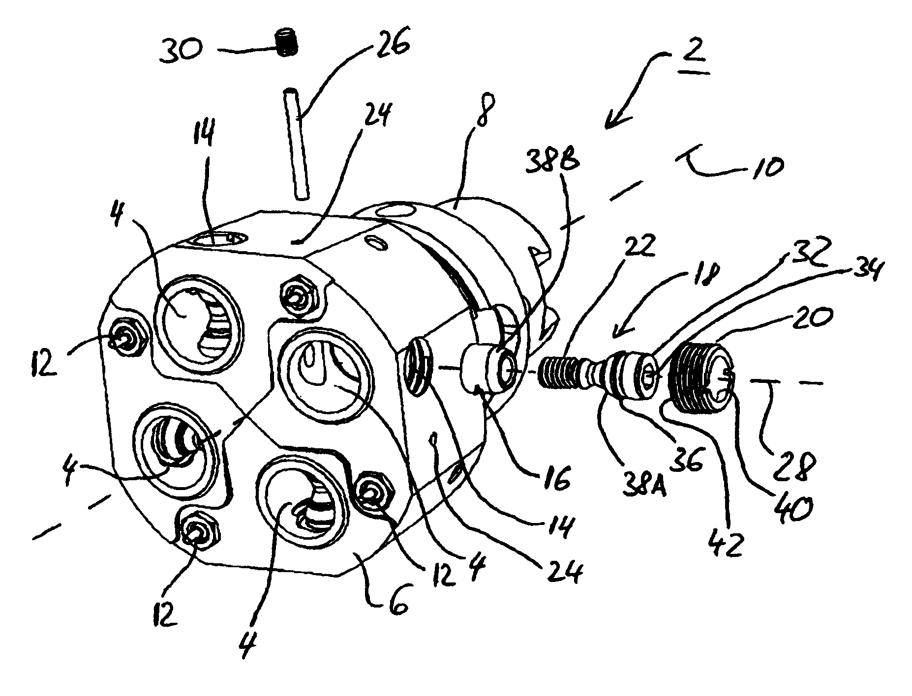
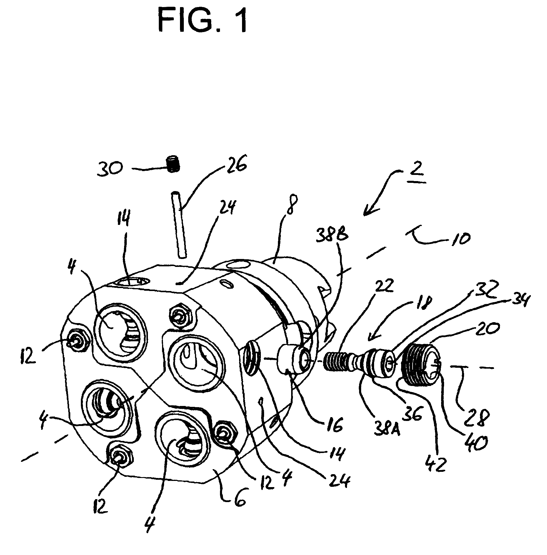
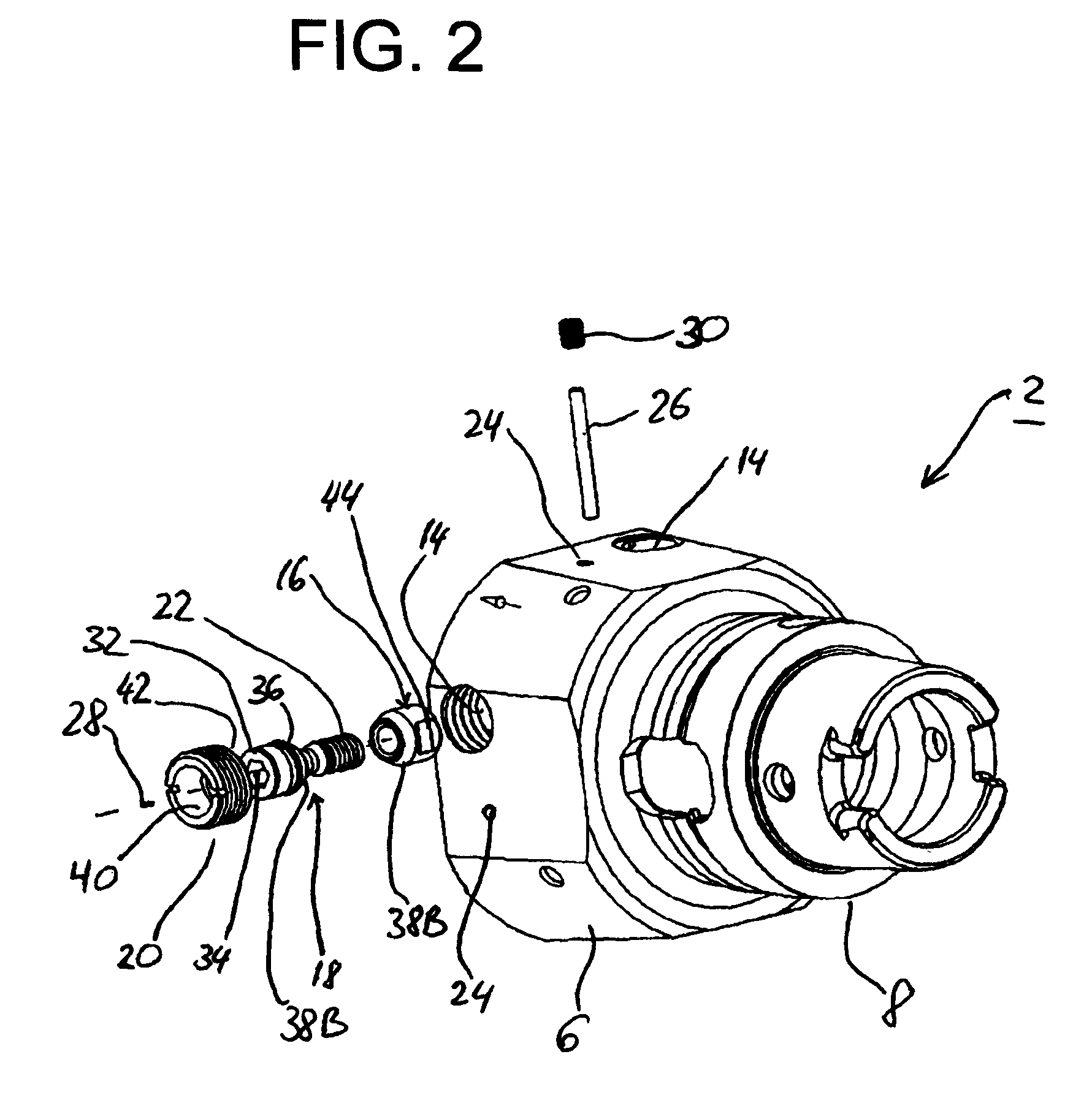
[0036]The tool holder 2 shown in FIGS. 1 and 2 serves to accommodate a total of four cutting tools (not shown in any more detail here). Said cutting tools are inserted at the end face from the front into corresponding tool receptacles 4 in the tool holder 2 and are then fastened in the tool receptacles 4 by means of a clamping device to be described in more detail below.

[0037]The tool holder 2 comprises a parent body 6 which is of one-piece monolithic design or alternatively has a plurality of tool carrying elements bearing against one another. In this case, each tool carrying element carries a respective tool receptacle 4. At its rear end, the parent body 6 has a shank 8 with which it is clamped in place in a corresponding receptacle of a machine tool. The tool holder 2 therefore extends from its front end face, in which the tool receptacles 4 are incorporated like bores, in the l...


PUM

PropertyMeasurementUnit
Diameteraaaaaaaaaa

Abstract

A cutting arrangement for cutting a workpiece having a tool holder which holds a plurality of cutting tools therein. The abstract of the disclosure is submitted herewith as required by 37 C.F.R. §1.72(b). As stated in 37 C.F.R. §1.72(b): A brief abstract of the technical disclosure in the specification must commence on a separate sheet, preferably following the claims, under the heading “Abstract of the Disclosure.” The purpose of the abstract is to enable the Patent and Trademark Office and the public generally to determine quickly from a cursory inspection the nature and gist of the technical disclosure. The abstract shall not be used for interpreting the scope of the claims. Therefore, any statements made relating to the abstract are not intended to limit the claims in any manner and should not be interpreted as limiting the claims in any manner.

Description

CONTINUING APPLICATION DATA[0001]This application is a Continuation-In-Part application of International Patent Application No. PCT / EP2007 / 008346, filed on Sep. 26, 2007, which claims priority from Federal Republic of Germany Patent Application No. 10 2006 052 051.3, filed on Nov. 4, 2006. International Patent Application No. PCT / EP2007 / 008346 was pending as of the filing date of this application. The United States was an elected state in International Patent Application No. PCT / EP2007 / 008346.BACKGROUND[0002]1. Technical Field[0003]The present application relates to a cutting arrangement for cutting a workpiece having a tool holder which holds a plurality of cutting tools therein. The present application further relates to a tool holder for accommodating cutting tools.[0004]2. Background Information[0005]Background information is for informational purposes only and does not necessarily admit that subsequently mentioned information and publications are prior art.[0006]During the mach...

Claims


Application Information

Patent Timeline
IPC IPC(8): B26D7/26
CPCB23B29/242Y10T82/2589Y10T407/2276B23B31/1077
Inventor PUSCHMANN-FRENKEN, JURGEN
Owner KENNAMETAL INC
Why Eureka
Try Eureka