Pipette Device System and Micropipette Thereof

a technology of pipette and device system, which is applied in the direction of analytical using chemical indicators, laboratory glassware, instruments, etc., can solve the problems of inconvenient manual micropipette, reduce work efficiency, and consume working time, and achieve simple structure, simple movement manner, and save space

Inactive Publication Date: 2010-05-06
OME TECH CO LTD
View PDF3 Cites 5 Cited by
  • Summary
  • Abstract
  • Description
  • Claims
  • Application Information

AI Technical Summary

Benefits of technology

[0010]A main object of the present invention is to provide a pipette device system and micropipette thereof which can implement multiple micro-dispensation in a simple movement manner and has the advantages of simple structure, saving space, easy maintenance and low costs.
[0014]When the rotating shaft rotates, the first, the second and the third connecting openings follow the rotating shaft to rotate, wherein the first connecting opening leaves the receiving hole to be connected with the engaging hole and the third connecting opening is synchronously switched to the receiving hole and connected with the receiving hole. At this time, quantitative liquid can be led to flowing into the receiving hole itself. When the rotating shaft rotates to the initial position so that the connecting hole can be connected with the receiving hole once again, the liquid can be discharged along the discharging hole. Accordingly, the present invention can implement the multiple micro-dispensation based on the simple structure and movement manner. The present invention has the advantages of simple structure, saving space, easy maintenance and low costs.

Problems solved by technology

Manual micropipettes require manual dispensation and thus entail a large amount of repetitive movements, which consumes working time and reduces work efficiency.
Since manual micropipettes are inconvenient for use, electronic micropipettes emerge as times require.
However, electronic micropipettes have complex structures, high manufacture costs and are difficult to maintain.
There are a lot of dispensation movements, so it needs a complex structure and large space to perform the dispensation movements described above when the micropipette is applied on automatic equipment.

Method used


Image

  • Pipette Device System and Micropipette Thereof
  • Pipette Device System and Micropipette Thereof
  • Pipette Device System and Micropipette Thereof

Examples


Embodiment Construction

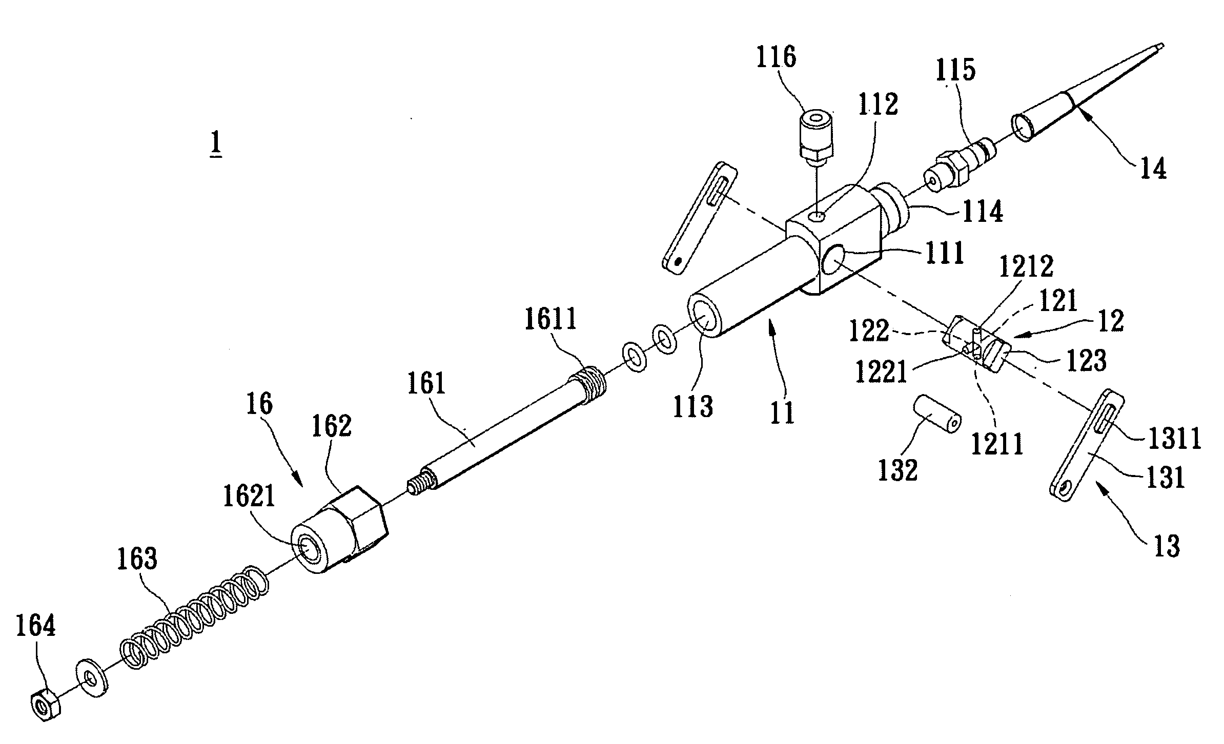
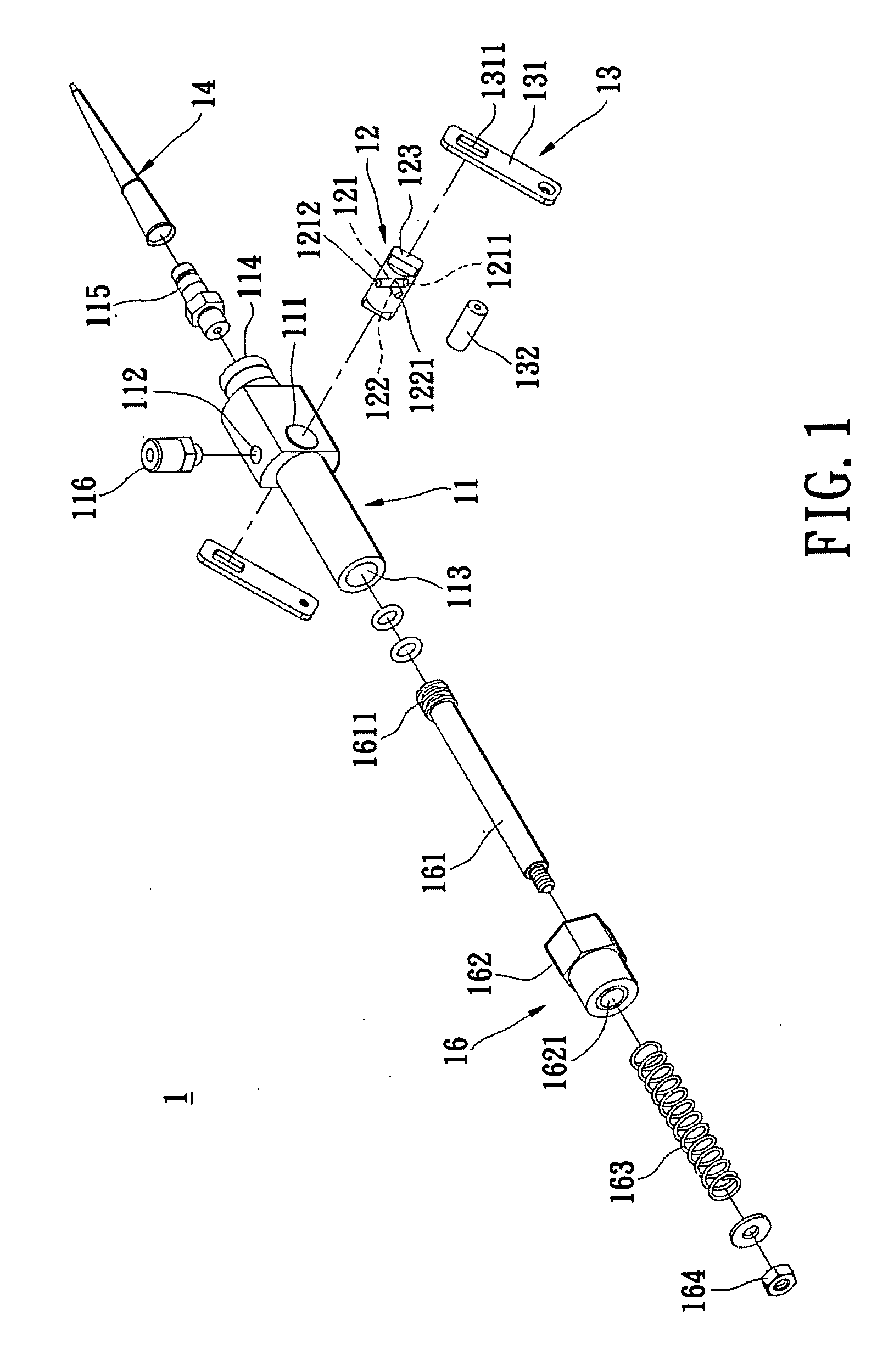
[0024]Please refer to FIGS. 1-8 illustrating a pipette device system and micropipette thereof according to the present invention. The micropipette 1 includes a pipe body 11, a rotating shaft 12, a swing member 13, a dispensing pipe 14, a flexible pipe 15 and a volume adjustment assembly 16.

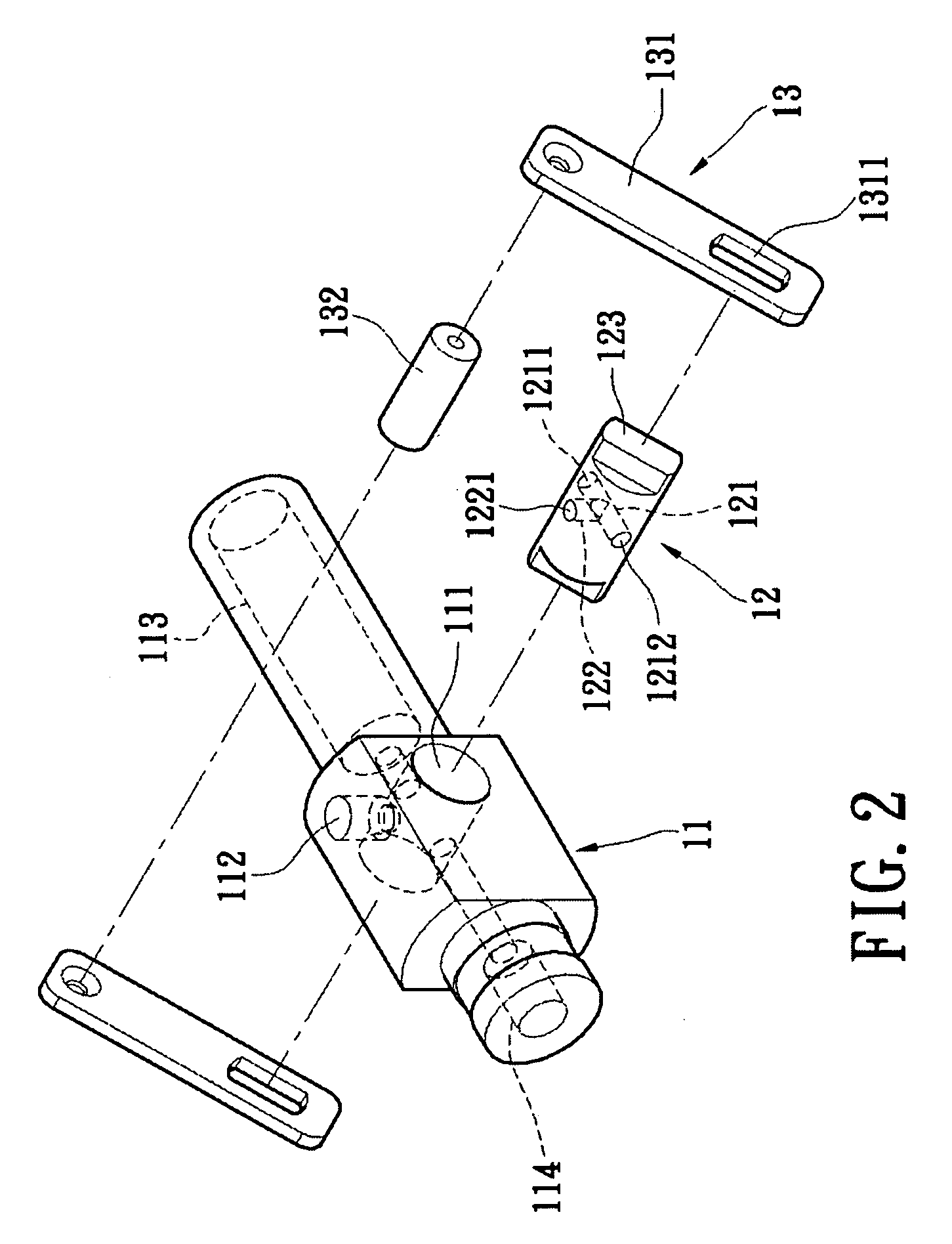
[0025]Please refer to FIGS. 1-3, the pipe body 11 has a rotating hole 111, an engaging hole 112, a receiving hole 113 and a discharging hole 114.

[0026]The rotating hole 111 and the engaging hole 112 are formed in the peripheral surface of the pipe body 11 in radial direction of the pipe body 11. The rotating hole 111 is a circular through-hole extending through the pipe body 11, which is orthogonally connected with the engaging hole 112 in the pipe body 11.

[0027]The discharging hole 114 is connected with the rotating hole 111 and axially formed in one end of the pipe body 11. The receiving hole 113 is formed in the pipe body 11, extends through the other end of the pipe body 11, and is connected w...


PUM


Abstract

A pipette device system and micropipette thereof is disclosed. The micropipette is disposed on the pipette device system and includes a pipe body, a rotating shaft and a swing member. A rotating hole and an engaging hole of the pipe body are connected with each other. A receiving hole and a discharging hole are formed in the pipe body and connected with the rotating hole. The rotating shaft is disposed in the rotating hole and has a connecting hole and a switching hole. A first connecting opening and a second connecting opening of the connecting hole are respectively connected with the receiving hole and the discharging hole. The switching hole has a third connecting opening and is connected with the connecting hole. The swing member is fixed on two ends of the rotating shaft. The present invention can implement the multiple micro-dispensation based on the simple structure and movement manner.

Description

BACKGROUND OF THE INVENTION[0001]1. Field of the Invention[0002]The present invention relates to a pipette device system and micropipette thereof, and more particularly to a pipette device system and micropipette thereof which can suck and discharge quantitative liquid.[0003]2. Description of Related Art[0004]Micropipettes are widely used in chemical laboratories, biological Laboratories, medical Laboratories and so on and occupy a decisive position not only on teaching experiments but also on practical medical engineering technology.[0005]Micropipettes can suck liquid in one vessel and transfer it into another vessel for liquid mixture or measurement operations. Depending on the micropipettes, related technicians can accurately control a liquid suction amount and a liquid discharge amount, thereby meeting the requirement of accurate experimental results.[0006]Conventional micropipettes generally include manual micropipettes and electronic micropipettes. Manual micropipettes require...

Claims


Application Information

Patent Timeline
Patent Type & Authority Applications(United States)
IPC IPC(8): B01L3/02
CPCB01L3/0217B01L2400/0478B01L2400/0644
Inventor DING, SHIH-HUNG
Owner OME TECH CO LTD
Why Eureka
Try Eureka