Vehicle

a technology for vehicles and vehicles, applied in the field of vehicles, can solve the problems that none of the related art techniques described in the above-referenced patent documents are, however, provided control to achieve raising and tilting without involving vehicle movemen

Active Publication Date: 2010-05-06
EQUOS RES
View PDF13 Cites 27 Cited by
  • Summary
  • Abstract
  • Description
  • Claims
  • Application Information

AI Technical Summary

Benefits of technology

[0006]It is therefore an object of the present invention to provide an inverted pendulum vehicle that can be raised, or tilted for a standstill for ingress and egress, without involving movement.
[0010]Further, the raising control means may determine a riding section target position for the riding section and a vehicle body tilt angle target value for the vehicle body according to the time elapsed from the start of raising, and performs feedback control of movement of the riding section according to the riding section target position and feedback control of the tilt of the vehicle body according to the vehicle body tilt angle target value.
[0011]Preferably, the raising control means determines the riding section target position and the vehicle body tilt angle target value such that the raising speed at the start and completion of raising is lower than the raising speed between start and completion of the raising.
[0017]In another embodiment, the vehicle includes: a limiting mechanism having a part that is in ground contact to thereby limit the tilt angle of the vehicle main body; a riding section movement mechanism moving the riding section relative to the vehicle body; a balancer which is movable relative to the vehicle body; ingress / egress standstill control means for tilting the vehicle main body to an ingress / egress standstill position in which the part of the limiting mechanism is in ground contact, while moving the riding section using the riding section movement mechanism; and balancer control means for controlling movement of the balancer so as to compensate for movement of the center of gravity of the vehicle main body that occurs as the vehicle main body is tilted by the raising control means.

Problems solved by technology

None of the related art techniques described in the above-referenced Patent Documents are, however, designed to bring the vehicle to a standstill stably with the vehicle in a tilted position.
Specifically, control to achieve raising and tilting without involving movement of the vehicle was not provided.

Method used


Image

  • Vehicle
  • Vehicle
  • Vehicle

Examples


first embodiment

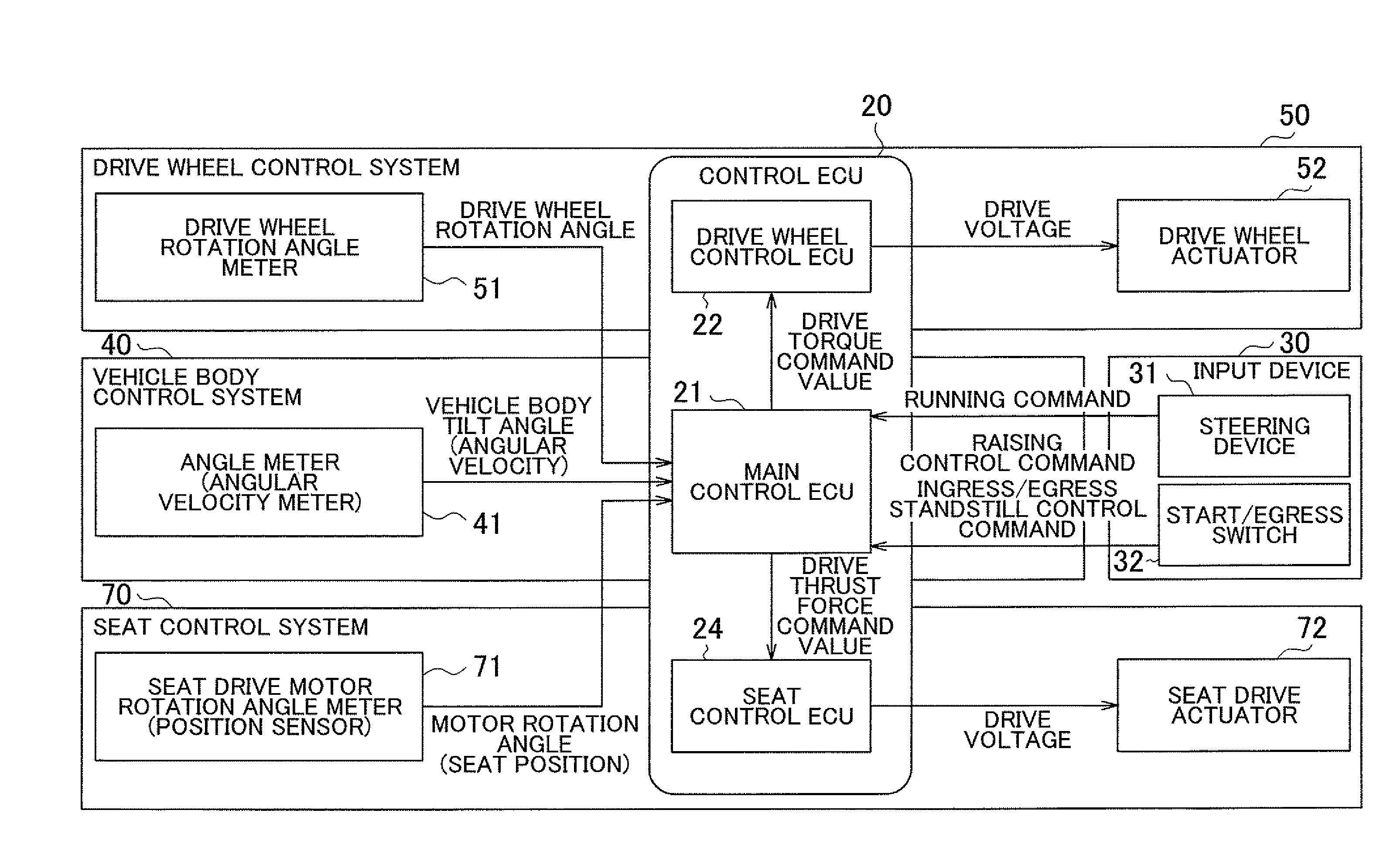
[0104]FIG. 3 is a block diagram of a control system according to the present invention.

[0105]The control system includes the control ECU 20 that functions as raising control means and ingress / egress standstill control means, the steering device 31, a start / egress switch 32, an angle meter (angular velocity meter) 41, a drive wheel rotation angle meter 51, a drive wheel actuator 52 (drive motor 12), a seat drive motor rotation angle meter (position sensor) 71, a seat drive actuator 72 (riding section drive motor), and other devices.

[0106]The control ECU 20 includes a main control ECU 21 and a drive wheel control ECU 22 and performs various types of controls including vehicle run and posture controls through, for example, drive wheel control and vehicle body control (inversion control). The control ECU 20 also includes a seat control ECU 24 for performing the raising and ingress / egress standstill controls through movement of the riding section 13 in this embodiment. The control ECU 20...

second embodiment

[0189]Referring to FIGS. 9A and 9B, the control system further includes a balancer control ECU 23, a balancer drive motor rotation angle meter 61, and a balancer drive actuator (motor) 62. The main control ECU 21 is adapted to function, together with these parts, as a balancer control system 60.

[0190]The balancer drive motor rotation angle meter (position sensor) 61 supplies the main control ECU 21 with a motor rotation angle corresponding to a balancer position. The main control ECU 21 supplies the balancer control ECU 23 with a drive thrust force command value. The balancer control ECU 23 supplies the balancer drive actuator 62 with a drive voltage corresponding to the drive thrust force command value.

[0191]Other arrangements are the same as those of the first embodiment described with reference to FIG. 3.

[0192]FIGS. 10A to 10C show exemplary configurations of different balancer movement mechanisms moving a balancer 134 to any desired position. The balancer movement mechanism fun...

third embodiment

[0243]Referring to FIG. 14, the control system includes a seat load meter 73 as part of the seat control system 70, and detects a riding section load (vertical load) WS and supplies the main control ECU 21 with the same.

[0244]In accordance with the third embodiment, the riding section mass is evaluated by using the load meter. Evaluation may still be made using a discrete measurement method, such as evaluating the mass with a simplified system in a stepwise fashion. Alternatively, the occupant may input his or her mass (weight) him / herself for use in evaluation.

[0245]Raising control and ingress / egress standstill control according to the third embodiment having arrangements as described above will be described below. Steps that are identical to those of the raising control and ingress / egress standstill control according to the first embodiment are assigned identical step numbers and descriptions thereof are omitted as appropriately.

[0246]FIG. 15 is a flowchart showing details of pro...


PUM


Abstract

A vehicle provides upstanding and tilted (standstill for allowing a user to get on an off the vehicle) positions without movement of the vehicle. In the vehicle, even if the vehicle body tilts, a riding section is moved in the forward-backward direction to bring the vehicle to an orientation where the center of gravity (P) of the vehicle body is on a vertical line (V) passing through ground contact points (S1) or drive wheels (12). This controls the tilt angle of the vehicle body and the position of the riding section (13) so that the center of gravity (P) does not move. Thus, the upright position and the tilted position of the vehicle are achieved without movement of the vehicle (without rotation of the wheels). Further, influences such as an error in parameters and disturbance are compensated for by a balancer that moves in the forward-backward direction.

Description

TECHNICAL FIELD[0001]The present invention relates to a vehicle, and for example, relates to a vehicle operating as an inverted pendulum for posture control.BACKGROUND ART[0002]Vehicles operating as an inverted pendulum for posture control (hereafter simply termed “inverted pendulum vehicles”) have attracted attention. A sensor unit provided in an inverted pendulum vehicle detects the operating state and a transportation device is placed in a stationary or moving state by controlling the operation of a rotating body by a control unit. JP-A-2004-74814 and JP-A-2004-217170 disclose provision of a retractable auxiliary wheel in such an inverted pendulum vehicle.[0003]JP-A-2004-74814 discusses facilitating the mounting and dismounting of the vehicle by a rider with ground contact of the extended auxiliary wheels to stabilize vehicle posture. Furthermore, extension of the auxiliary wheels maintains the vehicle posture when the posture control encounters difficult conditions. In JP-A-2004...

Claims


Application Information

Patent Timeline
Patent Type & Authority Applications(United States)
IPC IPC(8): G06F7/00B62K17/00A61G5/04
CPCA61G5/04B60N2/0244B60N2/24B62D37/04B62K11/007
Inventor DOI, KATSUNORI
Owner EQUOS RES
Why Eureka
Try Eureka