

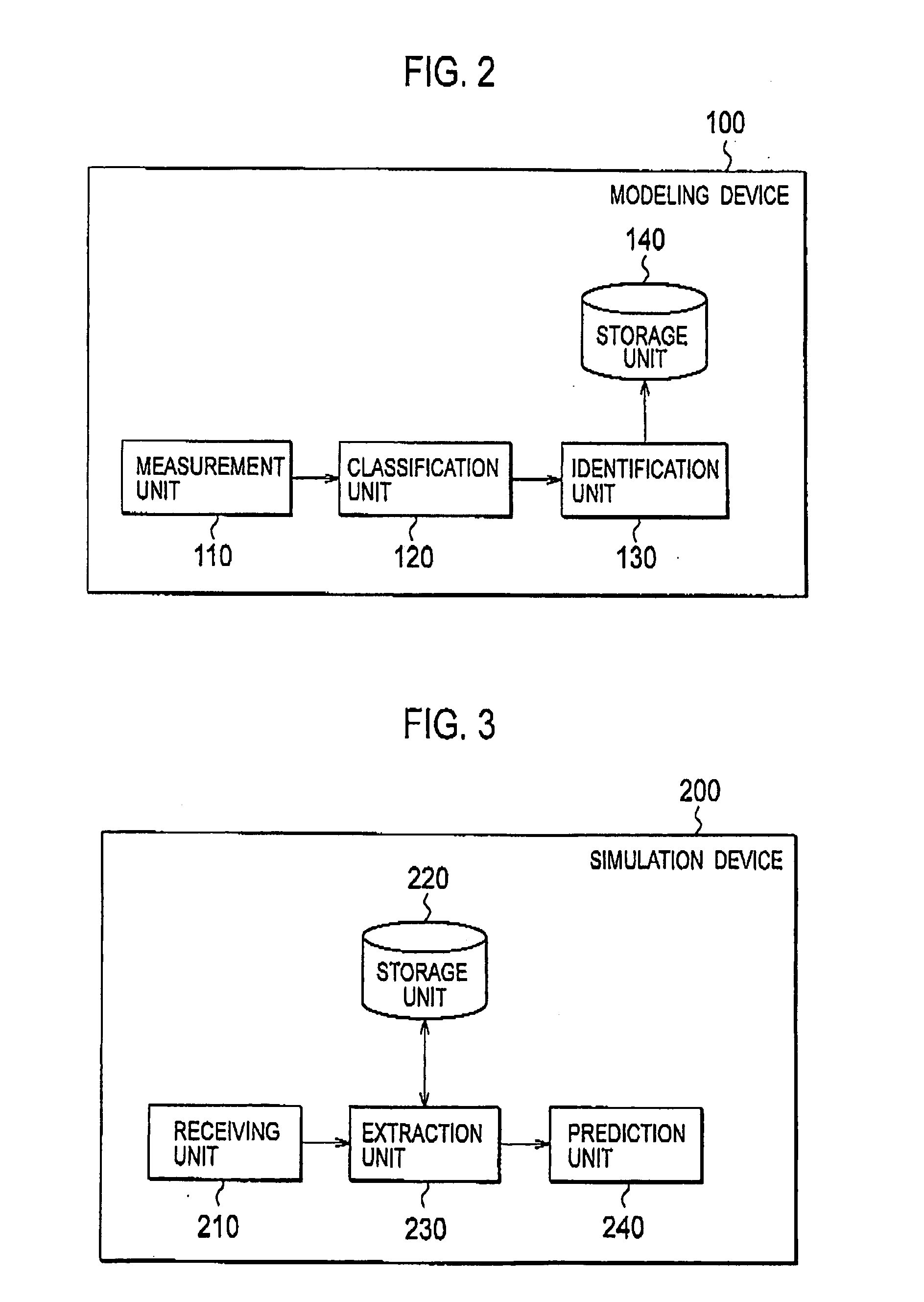
Modeling Device, Simulation Device, Modeling Program, Simulation Program, Method for Using Heat Balance Model, and System for Using Heat Balance Model
- Summary
- Abstract
- Description
- Claims
- Application Information
AI Technical Summary
Benefits of technology
Problems solved by technology
Method used
Image

Examples
first embodiment
Outline of Heat Balance Model
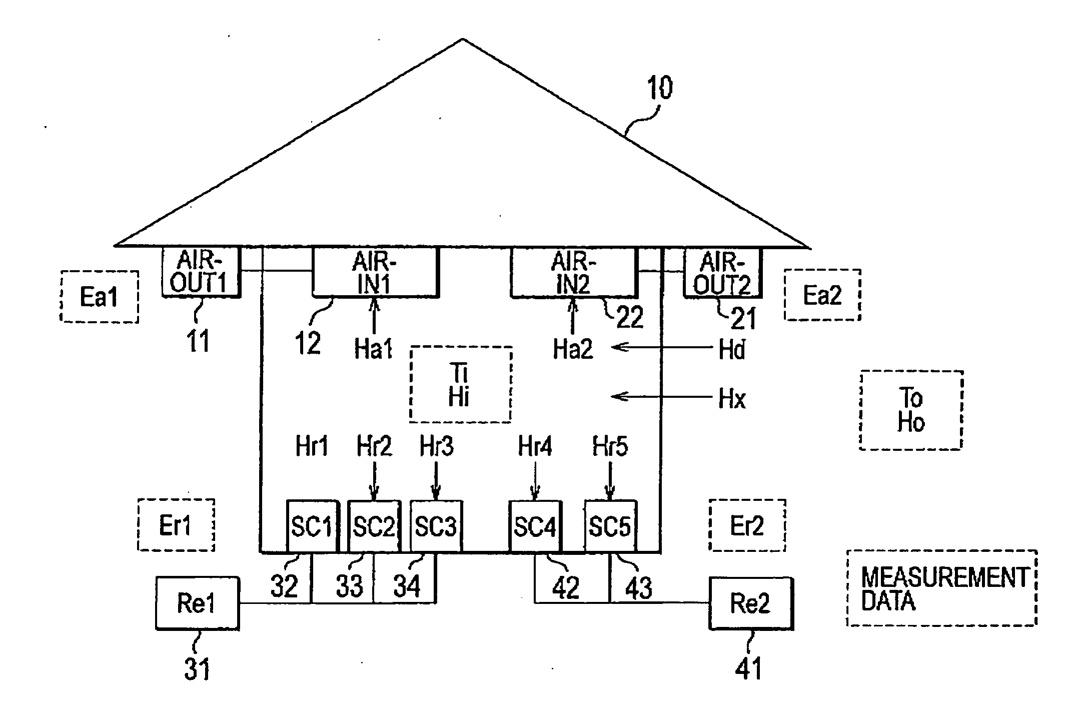
[0060]Description will be given below with reference to the drawings, with regard to an outline of a heat balance model according to a first embodiment of the present invention. FIG. 1 is a diagram showing the outline of the heat balance model according to the first embodiment of the present invention.
[0061]As shown in FIG. 1, a facility 10 contains a plurality of equipments (e.g., an outdoor unit 11, an indoor unit 12, an outdoor unit 21, an indoor unit 22, a condensing unit 31, showcases 32 to 34, a condensing unit 41, and showcases 42 and 43).
[0062]The facility 10 contains a plurality of equipments that affect heat balance in the facility 10, and is, for example, a convenience store, a supermarket, or the like.
[0063]An air conditioner (including the outdoor unit 11 and the indoor unit 12) is the air conditioner that controls temperature or humidity in the facility 10. Likewise, an air conditioner (including the outdoor unit 21 and the indoor unit 22) ...
examples
[0167]Description will be given below with reference to the drawings, with regard to examples of the present invention. Specifically, description of examples of various tables stored in the modeling device 100, description of an example of parameter identification, and description of an example of the concept of a method for selecting classification conditions according to the type of the facility 10 will be given in this order. Incidentally, it should be noted that the following examples are illustrative only, and the present invention is not limited to these examples.
(Example of Table)
[0168]FIG. 9 is a table showing an example of a table according to an example of the present invention. As shown in FIG. 9, the modeling device100 stores a measurement data table, a day / season table, a weather table, a weather information table, an equipment operation mode table, and the like.
[0169]The measurement data table is the table containing the measurement data (e.g., the temperature and humi...
second embodiment
[0197]Description will be given below with reference to the drawing, with regard to a second embodiment of the present invention. Description will be given below mainly with regard to the points of difference between the above-mentioned first embodiment and the second embodiment.
[0198]Specifically, in the above-mentioned first embodiment, the facility 10 is provided with the air conditioners, the condensing units and the showcases. On the other hand, in the second embodiment, the facility 10 is provided with the air conditioners alone and is not provided with the condensing units and the showcases.
(Outline of Heat Balance Model)
[0199]Description will be given below with reference to the drawing, with regard to an outline of a heat balance model according to the second embodiment of the present invention. FIG. 16 is a diagram showing the outline of the heat balance model according to the second embodiment of the present invention.
[0200]As shown in FIG. 16, the facility 10 contains a ...
PUM
 Abstract
Description
Claims
Application Information