Signage system

a technology of signage and system, applied in the field of signage system, can solve problems such as incorrect presentation of composite messages

Inactive Publication Date: 2010-05-13
KONINKLIJKE PHILIPS ELECTRONICS NV
View PDF4 Cites 18 Cited by
  • Summary
  • Abstract
  • Description
  • Claims
  • Application Information

AI Technical Summary

Benefits of technology

[0005]It is an object of the present invention to address this issue, and to provide an improved signage system, the displays of which easily can be synchronized.
[0009]In one embodiment, each control signal is a light signal and the detection means is a photo detector, whereby detection of the light by the photo detector may trigger the displays. Preferably, the light signal is an infrared signal (IR) and the photo detector is an IR detector. Transmission via infrared technology is well known per se, and relatively easy and cheap to implement. In a further embodiment, the control means is further adapted to select a display content to be showed on the display in accordance with the frequency and / or modulation of the detected light signal. For instance, an IR signal from the central unit having a first modulation can initiate the display of a first image or animation or play list (with images / animations, for example), and an IR signal having a second, different modulation can initiate the display of a second, different image or animation or play list. Thus, by emitting IR signals with different modulation (and / or frequency), the central unit can control the contents of the displays. Further, when using an infrared signal, the central unit is preferably a wide beam infrared remote control, so that the displays of several textile products can be initiated all at once. Instead of an infrared signal, a flash light or any visible or non-visible light of a dedicated frequency could be used to trigger the displays.

Problems solved by technology

However, an issue when using multiple displays, especially for presenting a dynamic composite message, is that the operation of the individual displays may have to be synchronized; otherwise the composite message may not be presented correctly.

Method used


Image

  • Signage system
  • Signage system

Examples


Embodiment Construction

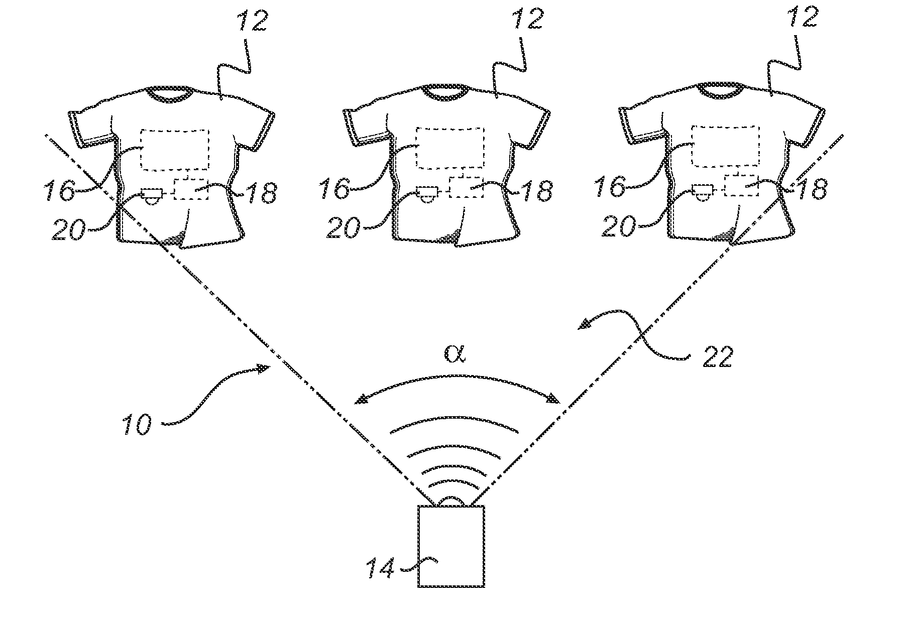
[0019]FIG. 1 schematically illustrates a signage system 10 according to an embodiment of the invention. The system 10 comprises plurality of textile products 12, which in FIG. 1 are garments, more precisely shirts. Alternatively, the textile products 12 may be other garments, such as jackets or vests, or a piece of furniture, a bag, etc. Each shirt 12 comprises a flexible display device 16 (in the following “display”16). The display 16 is installed behind the outer cloth of the shirt 12. Preferably, the display 16 comprises a plurality of light emitting diodes (LEDs) mounted on a flexible substrate (not shown). Such an LED display can be made relatively thin and flexible, and is power efficient, which is especially beneficial when used in a shirt. When the display 16 is on, an illuminated image or animation or other message may be shown through the outer cloth on the shirt 12. On the other hand, when the display 16 is off, the display 16 is hardly visible from outside the shirt 12.

[...


PUM


Abstract

The present invention relates to a signage system (10) comprising: a plurality of textile products (12) each comprising a flexible display device (16). For controlling the displays (16), the system further comprises a central unit (14, 24) adapted to emit at least one control signal, each of which being a sound signal or a light signal. To this end, each textile product further comprises means (20, 26) for detecting the control signal(s) emitted by the central unit (14, 24), and means (18) linked to the detection means (20, 26) and display (16) for controlling the display (16) in accordance with the detected control signal(s). The present invention also relates to a method, central units and uses of such for controlling a plurality of flexible display devices each comprised in a textile product.

Description

FIELD OF THE INVENTION[0001]The present invention relates to a signage system comprising a plurality of textile products each comprising a flexible display device. The present invention also relates to a method, central units and uses of such for controlling a plurality of flexible display devices each comprised in a textile product.BACKGROUND OF THE INVENTION[0002]An example of a textile product comprising a flexible display device is disclosed in WO2006 / 014230. More precisely, WO2006 / 014230 describes a flexible display screen with a plurality of light emitting diodes acting as pixels in a matrix pattern. The display is installed in a jacket. The display may for instance be held by a pocket or pouch in proximity to the outer cloth of the jacket, which pocket or pouch resides inside the lining of the jacket. The display is controlled by a control circuit connected to it, and the system is powered by a battery pack. Both the control circuit and battery pack may also be placed within ...

Claims


Application Information

Patent Timeline
Patent Type & Authority Applications(United States)
IPC IPC(8): A41B1/00G09G5/00G09G3/32H04Q5/22H04R3/00G10L15/00A41D1/00
CPCA41D1/002A41D13/01G06F3/1446G06F3/147G08B5/004G09F21/02G09G2300/026G09G2380/06G06F3/14
Inventor KRANS, MARTIJNBERGMAN, ANTHONIE HENDRIKVAN DE SLUIS, BARTEL MARINUSZAINZINGER, ERICHZEPER, WOUTER BASTIAANLAMERICHS, GUIDO THEO MARIASCHULER, THOMAS
Owner KONINKLIJKE PHILIPS ELECTRONICS NV
Why Eureka
Try Eureka