Method and system for scatter correction

a scatter correction and scattering technology, applied in the field of methods, can solve the problems of degrading image contrast, additional counts that the scatter model attempts to correct, and causing background

Active Publication Date: 2010-05-13
GENERAL ELECTRIC CO
View PDF9 Cites 21 Cited by
  • Summary
  • Abstract
  • Description
  • Claims
  • Application Information

AI Technical Summary

Problems solved by technology

Moreover, scattered radiations increase the background to the image, thus degrading the image contrast.
However, in addition to the scatter caused by annihilation of the 511 keV gamma photons, other radiopharmaceuticals used in PET imaging may cause additional counts that the scatter model attempts to correct.
The background effect caused by the 777 keV annihilation events is problematic to the conventional scatter correction model.
Because the conventional scatter correction algorithm models use only the data representing the 511 keV annihilation events to estimate the scatter correction, the background effect caused by the 777 keV annihilation events causes a mis-scaling of the scatter correction.

Method used


Image

  • Method and system for scatter correction
  • Method and system for scatter correction
  • Method and system for scatter correction

Examples


Embodiment Construction

[0018]The foregoing summary, as well as the following detailed description of certain embodiments of the present invention, will be better understood when read in conjunction with the appended drawings. To the extent that the figures illustrate diagrams of the functional blocks of various embodiments, the functional blocks are not necessarily indicative of the division between hardware circuitry. Thus, for example, one or more of the functional blocks (e.g., processors or memories) may be implemented in a single piece of hardware (e.g., a general purpose signal processor or a block of random access memory, hard disk, or the like). Similarly, the programs may be stand alone programs, may be incorporated as subroutines in an operating system, may be functions in an installed software package, and the like. It should be understood that the various embodiments are not limited to the arrangements and instrumentality shown in the drawings.

[0019]As used herein, an element or step recited i...


PUM


Abstract

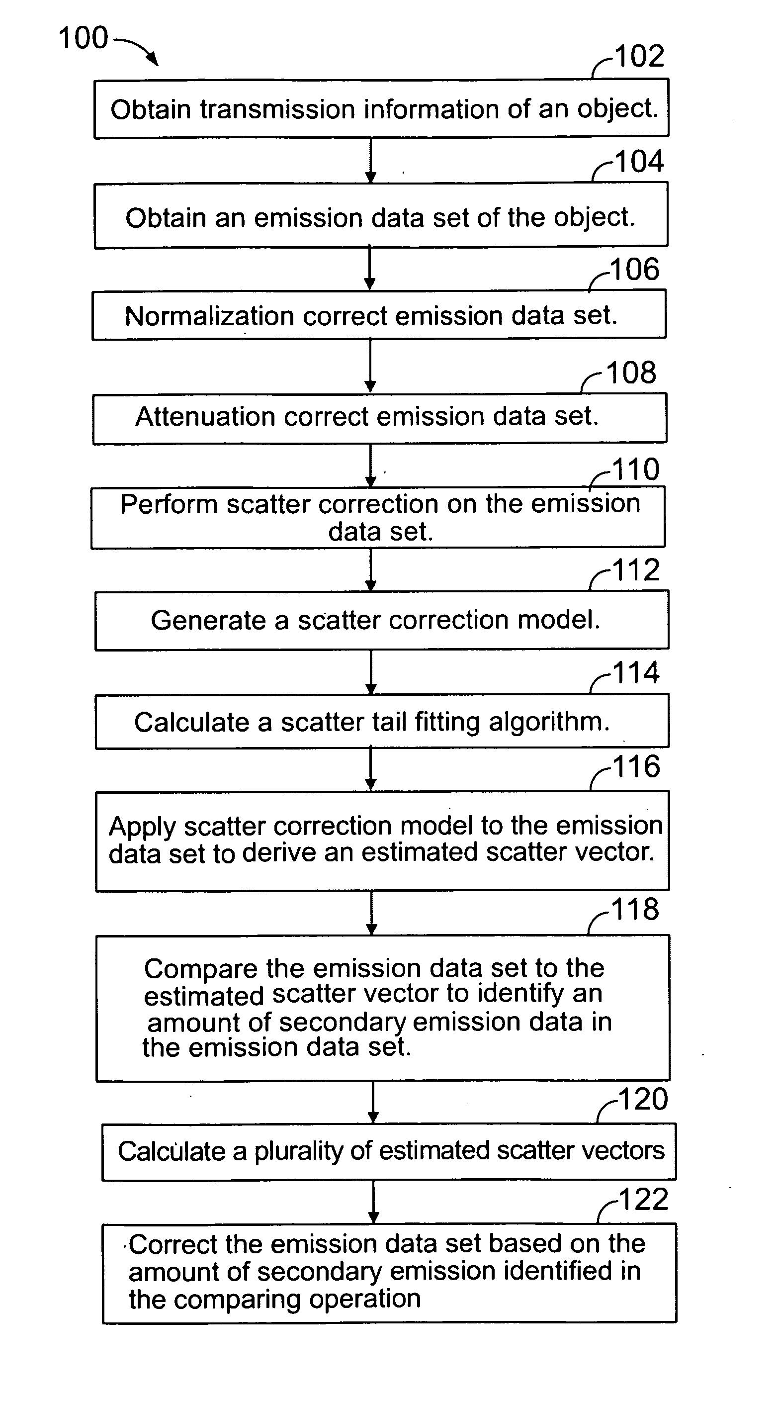
A method and apparatus are provided for correcting primary and secondary emission data. The method includes obtaining an emission data set having primary and secondary emission data representative of primary and secondary emission particles emitting from a region of interest and applying a scatter correction model to the emission data set to derive an estimated scatter vector. The method also includes comparing the emission data set to the estimated scatter vector to identify an amount of secondary emission data in the emission data set and correcting the emission data set based on the amount of secondary emission data identified in the comparing operation.

Description

BACKGROUND OF THE INVENTION[0001]The invention relates generally to imaging systems, and more particularly, embodiments relate to a method and system for correcting scatter generated by a multi-modality imaging system.[0002]Multi-modality imaging systems exist that scan using different modalities, such as, for example, Positron Emission Tomography (PET), Single Photon Emission Computed Tomography (SPECT), and Computed Tomography (CT). During operation of a PET imaging system, for example, a patient is initially injected with a radiopharmaceutical that emits positrons as the radiopharmaceutical decays. The emitted positrons travel a relatively short distance before the positrons encounter an electron, at which point an annihilation occurs whereby the electron and positron are annihilated and converted into two gamma photons each having an energy of 511 keV.[0003]The annihilation events are typically identified by a time coincidence between the detection of the two 511 keV gamma photo...

Claims


Application Information

Patent Timeline
Patent Type & Authority Applications(United States)
IPC IPC(8): G01T1/164G01R13/00
CPCG01T1/1611G01T1/1648
Inventor WOLLENWEBER, SCOTT DAVIDMCDANIEL, DAVID LEOSTEARNS, CHARLES WILLIAM
Owner GENERAL ELECTRIC CO
Why Eureka
Try Eureka