Suspension device

Inactive Publication Date: 2010-05-13
KYB CORP
View PDF12 Cites 19 Cited by
  • Summary
  • Abstract
  • Description
  • Claims
  • Application Information

AI Technical Summary

Benefits of technology

[0010]According to the suspension device of the present invention, when a high-frequency vibration acts on the unsprung member, the drawback that the vibration is apt to be transmitted to the sprung member under the influence of moment of inertia in the actuator is remedied, whereby it is possible to improve the ride comfort in the vehicle.
[0011]Also in the event of striking on a projection or passing a depression during a turning motion, it is possible to surely prevent a bottom contac

Problems solved by technology

However, the above conventional dampers involve the following problem.
On the other hand, if the actuator can retract without resistance, the foregoing vibration is not transmitted to the sprung member side, but since the moment of inertia of the rotor of the motor in the actuator is lar

Method used


Image

  • Suspension device
  • Suspension device
  • Suspension device

Examples


Embodiment Construction

[0022]The present invention will be described below by way of embodiments thereof illustrated in the drawings.

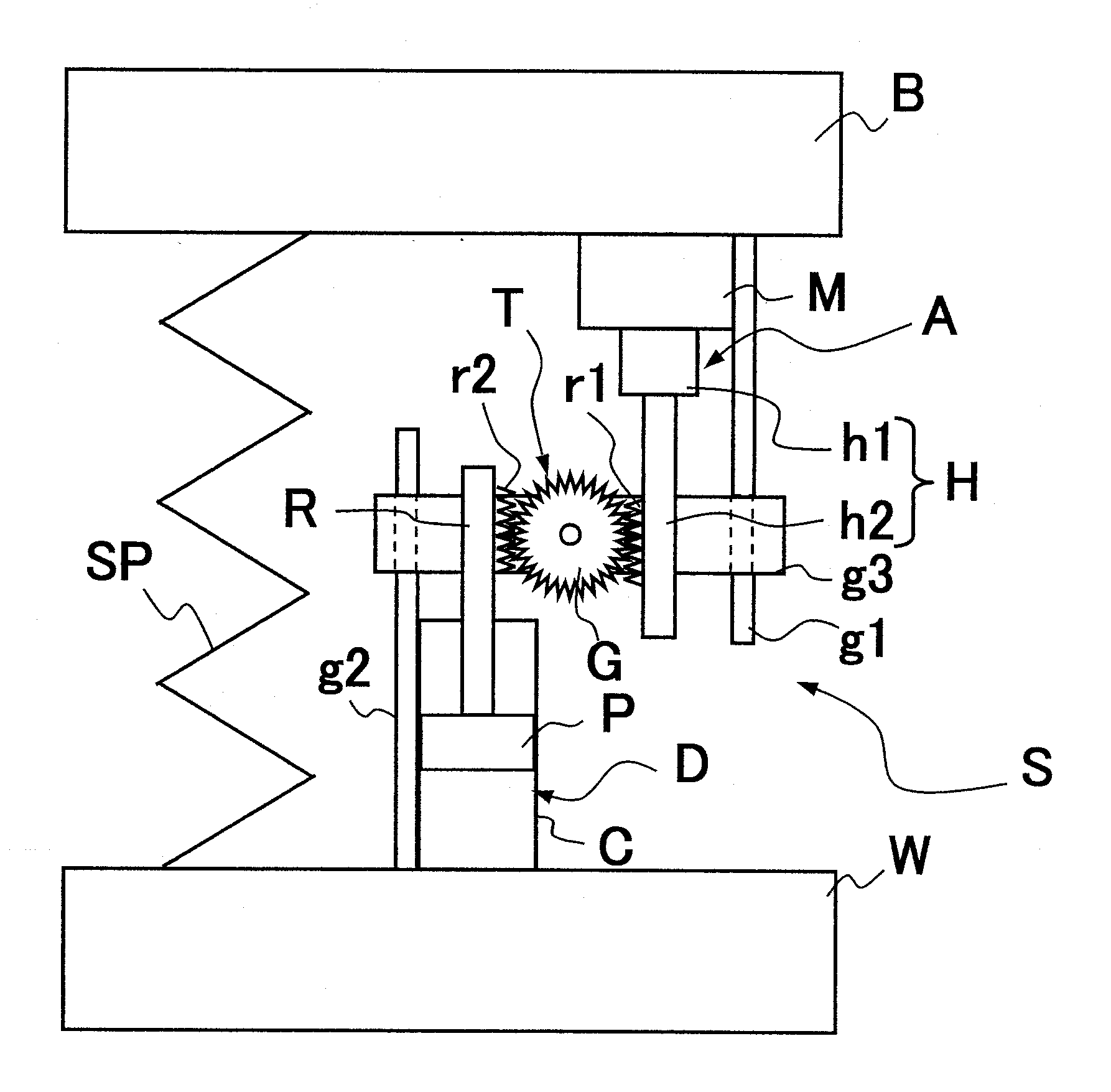
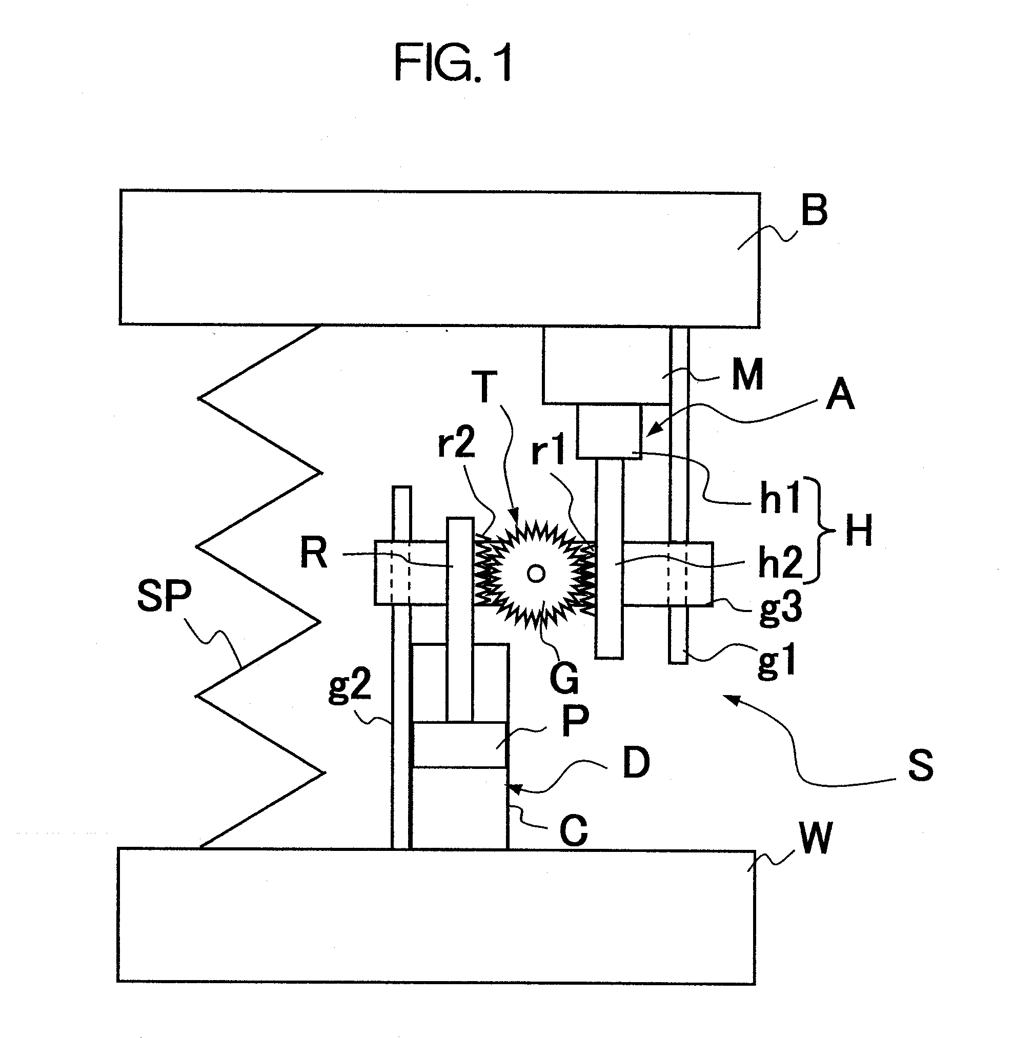
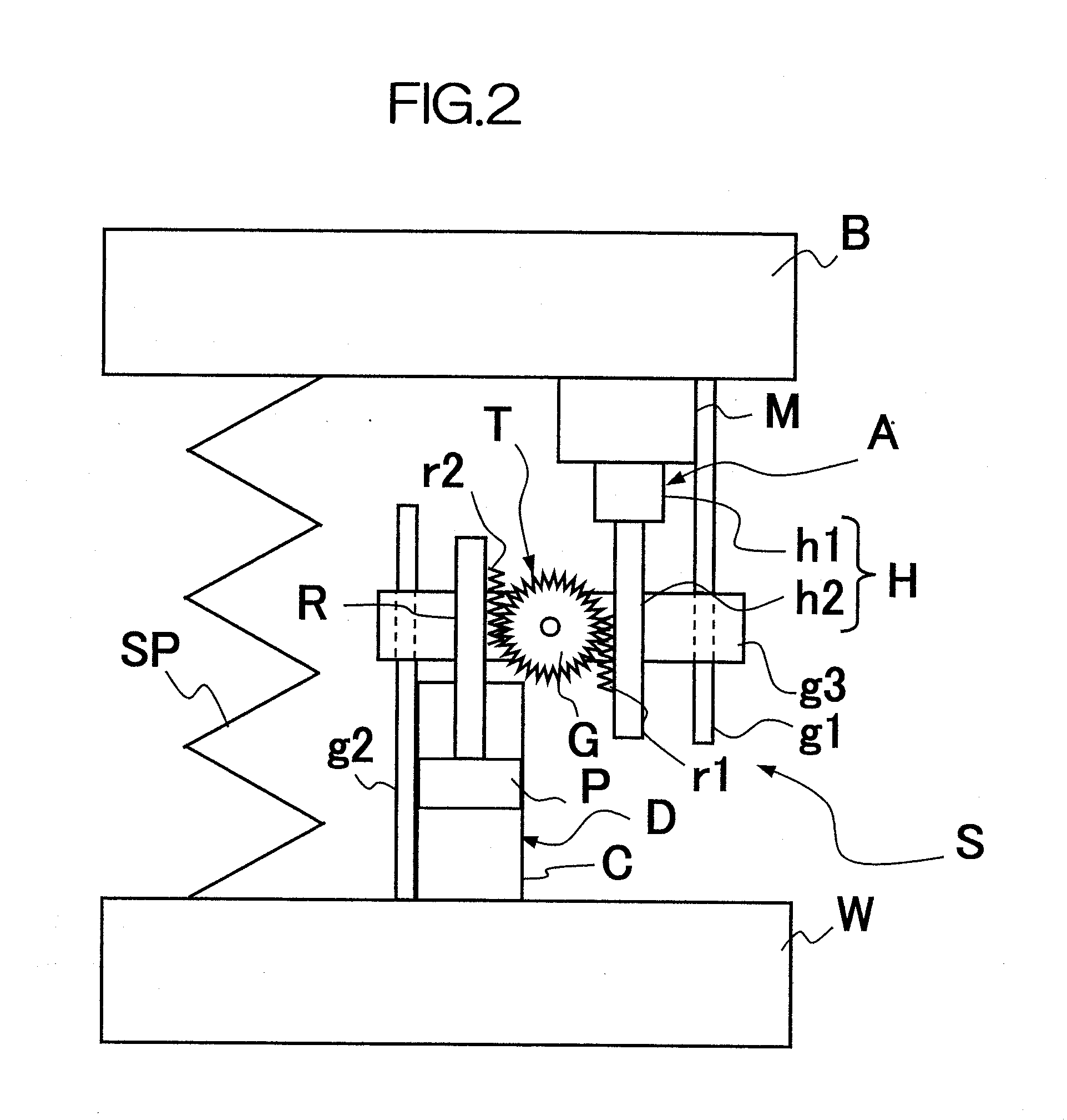
[0023]As shown in FIG. 1, a suspension device S according to an embodiment of the present invention includes an actuator A, a hydraulic damper D, and a direction changing mechanism T for changing a linear motion of the actuator A into a linear motion in an opposite direction and transmitting the opposite linear motion to the hydraulic damper D. The suspension device S is interposed between a sprung member B and an unsprung member W in a vehicle.

[0024]The actuator A includes a motion transforming mechanism H for transforming a linear motion into a rotational motion and a motor M to which the rotational motion obtained by the motion transforming mechanism H is transmitted. The motion transforming mechanism H includes a rotating member h1 connected directly or indirectly to a rotor (not shown) of the motor M and performing a rotational motion and a linear motion member h2 adapt...


PUM


Abstract

A suspension device S interposed between a sprung member B and an unsprung member W of a vehicle, comprising an actuator A, a hydraulic damper D, and a direction changing mechanism T for changing a linear motion of the actuator A into a linear motion in an opposite direction and transmitting the opposite linear motion to the hydraulic damper D. When a high-frequency vibration acts on the unsprung member, the drawback that the vibration is apt to be transmitted to the sprung member B under the influence of moment of inertia of the actuator A is remedied and it is possible to improve the ride comfort in the vehicle.

Description

FIELD OF ART[0001]The present invention relates to an improvement of a suspension device.BACKGROUND ART[0002]As a suspension device of this type, there has been proposed a damper comprising a hydraulic damper and an actuator for imparting a propelling force to a piston rod of the hydraulic damper, as is disclosed in Japanese Patent Laid-Open Publication No. 2001-180244. According to this proposal, a rod of the hydraulic damper is formed in a cylindrical shape, an internal thread portion is formed on an inner periphery side of the rod, a shaft connected at one end thereof to a rotor of a motor and at an opposite end thereof to an external thread member which is threadably engaged with the internal thread portion of the rod of the hydraulic damper, and the shaft is inserted through the rod, and thus, the piston rod of the hydraulic damper is constituted by the shaft and the rod (see, for example, Patent Literature 1).[0003]According to the above proposal, force which is produced at th...

Claims


Application Information

Patent Timeline
IPC IPC(8): F16F15/03B60G17/00
CPCB60G13/18B60G17/0157B60G17/021B60G17/08B60G2202/42B60G2202/442F16F15/02B60G2204/4192B60G2204/421B60G2800/012B60G2800/162F16F7/10B60G2204/419
Inventor OHTA, YASUHIROKONDO, TAKUHIRO
Owner KYB CORP
Why Eureka
Try Eureka