Method and apparatus for effecting relative movement of containers

a technology of relative movement and container, applied in the direction of transportation and packaging, load-engaging elements, trolleys, etc., can solve the problems of significant loss of lifting capacity, maintenance problems, maintenance problems, etc., and achieve the effect of being easily detachable from the cran

Active Publication Date: 2010-05-13
RAM SMAG ELEVATORING TECHNOLOGOES PTE LTD
View PDF4 Cites 3 Cited by
  • Summary
  • Abstract
  • Description
  • Claims
  • Application Information

AI Technical Summary

Benefits of technology

[0009]Therefore, the invention provides for the sheaves of a first head block to be transferred to a second, and so releasing the first head block for maintenance. Similarly, it may be possible to remove the sheave pins of all the sheaves, and so detaching both head blocks permitting replacement head blocks to be attached to the sheaves or alternatively a single head block attached to both sheaves for continued used of the crane. In any event, it is not necessary for cables to be removed from the sheaves in order to maintain the crane in useful operation whilst maintenance is carried out.
[0010]In a preferred embodiment, the separation device may be disengageable from the second head block such that the first head block retains the separation device. Accordingly the first head block and the separation device could both be sent to the workshop for maintenance without disengaging the cables from the sheaves and so maintaining the crane in operation.
[0011]In a preferred embodiment, the hydraulic systems, actuators and linkages associated with the separation device may also be mounted on the first head block. In this case the remaining portion of the assembly may be the second head block and sheaves associated with both head blocks. Being substantially heavy machinery, the frequency for maintenance is much less as compared to the separation device. Accordingly that portion of the total assembly that requires maintenance more frequently is that which is more easily detachable from the crane.

Problems solved by technology

A characteristic of these multi-container devices is the problem of maintenance and the length of “downtime” of this capital intensive equipment.
If a problem arises with one of the head blocks, it is necessary to remove the entire device from the crane including disengaging the cables from the sheaves.
As the separation mechanism between the head blocks uses a considerable number of actuators, this may be a significant cause of maintenance problems.
The time taken to remove and then replace the device on the crane, so as to make the crane functional, is considerable leading to significant loss of lifting capacity.
Another drawback of these types of devices is the complexity that goes into their manufacture.
Typically they are large complicated devices requiring significant engineering and control over the large number of actuators involved with their operation.
The control system or operator control needs to be complex in order to operate the device, not only for separation of the containers attached to the head blocks, but also to change their relative position, such as by “skewing” the containers, which requires operation of one set of actuators only.

Method used


Image

  • Method and apparatus for effecting relative movement of containers
  • Method and apparatus for effecting relative movement of containers
  • Method and apparatus for effecting relative movement of containers

Examples


first embodiment

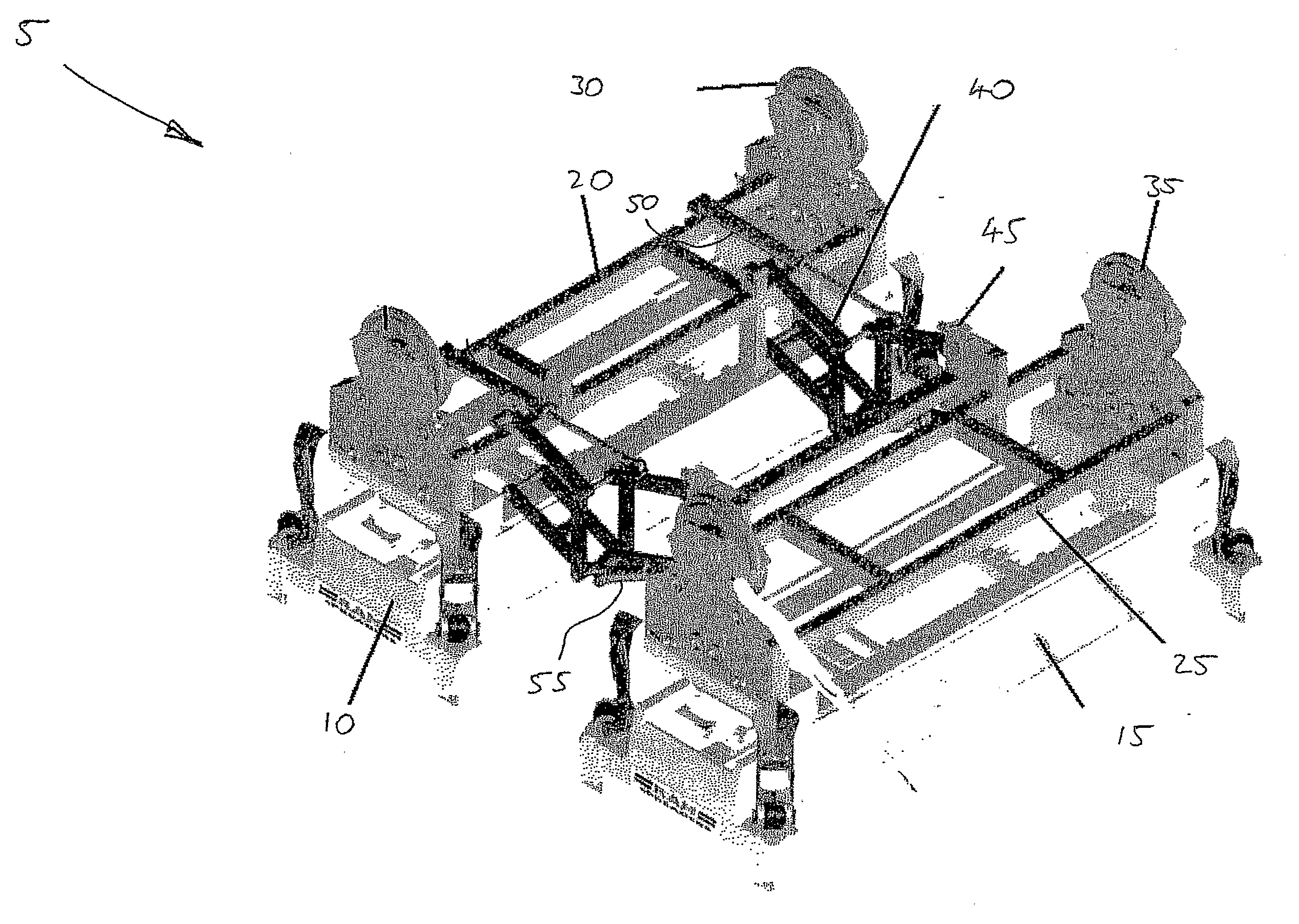
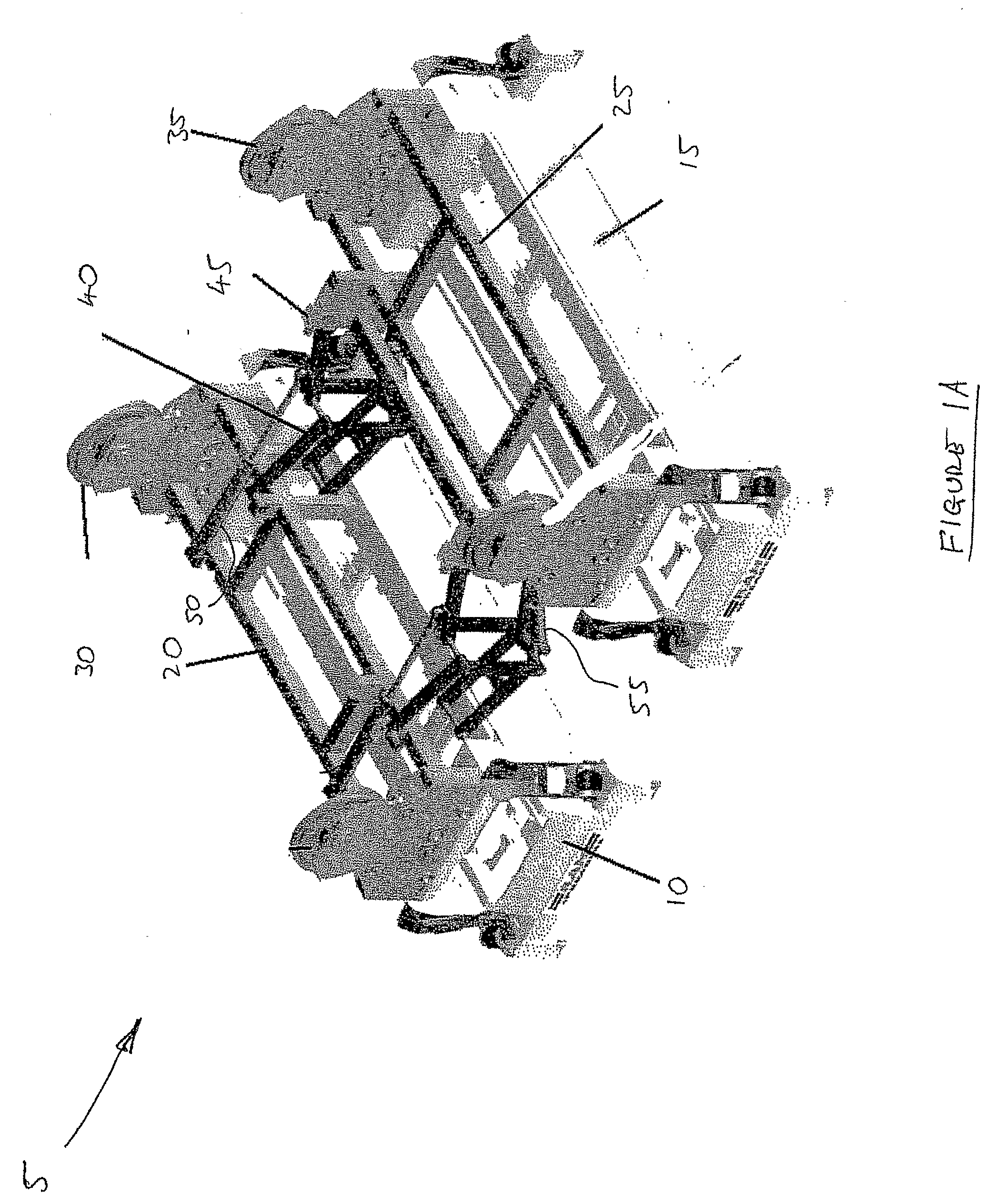
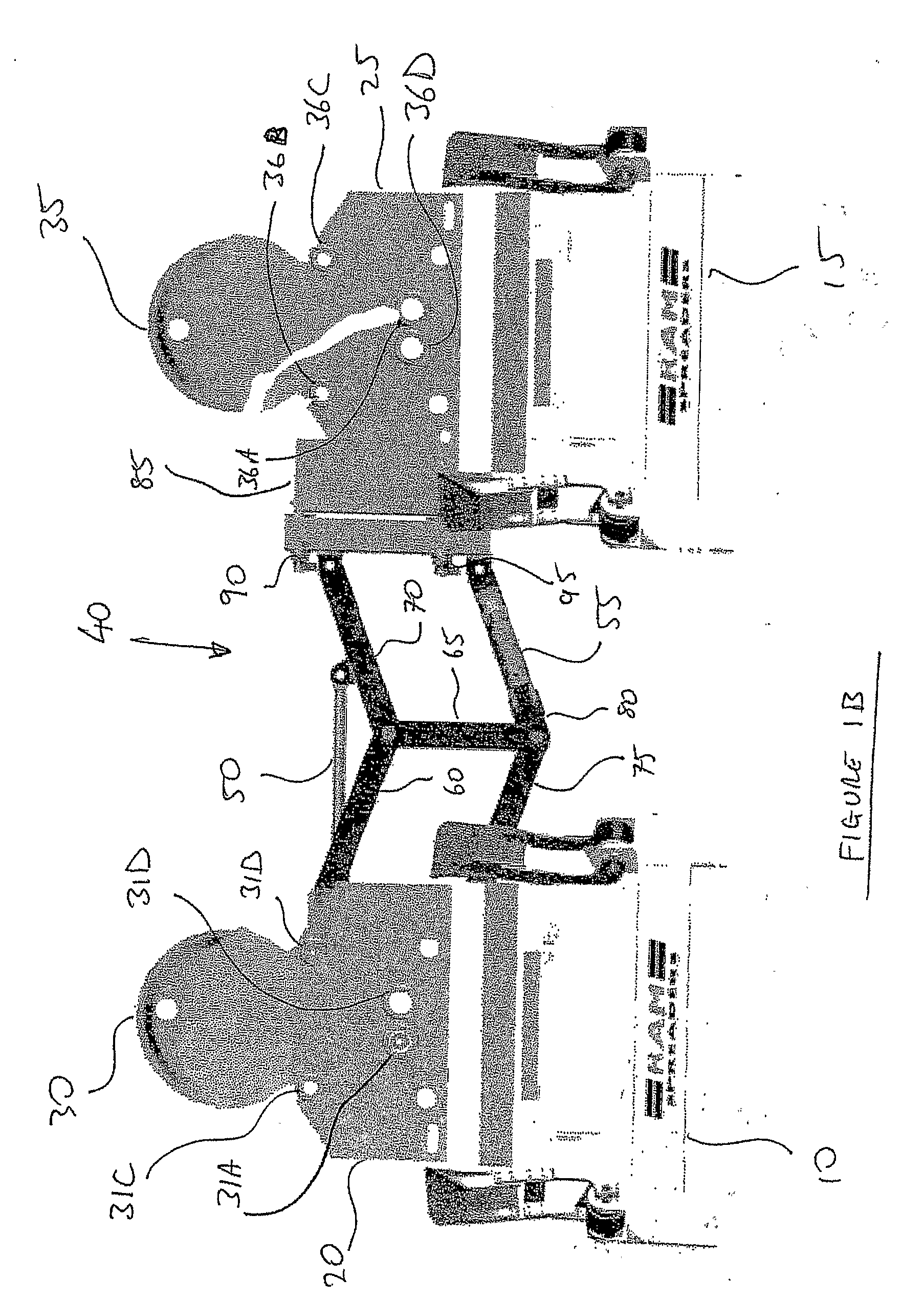
[0038]FIGS. 1A and 1B show the engagement device 5 according to the present invention. Here the device has engaged two spreaders 10, 15 beneath respective coupled head blocks 20, 25. The head blocks 20, 25 are coupled through a separation device 40 mounted between the head blocks 20, 25. Specifically, the separation device 40 is mounted to a first head block 20 which is extended out so as to engage with the second head block 25 through twist locks 90, 95. The twist locks 90, 95 are engaged with a bracket 85 mounted on the second head block 25 so as to make the releasable connection between the head blocks 20, 25.

[0039]In this embodiment, the head blocks 20, 25 have attached thereto a pair of sheaves 30, 35 with one sheave at either end of each head block, making it a total of four. Each head block 20, 25 includes four sheave pin locations 31A to D, 36A to D. Whilst engagement of one sheave requires only two such locations, by providing four, the each head block is capable of acting ...

second embodiment

[0045]FIG. 6A and 6B show a second embodiment falling within the scope of the present invention. Here, two head blocks 120, 125 are again mounted to spreaders 110, 115. The head blocks 120, 125 are connected through a separation device 140 which effects relative transverse movement between the head blocks 120, 125. As with the previous embodiment each head block includes a pair of sheaves 130, 135 for engagement with cables coming from a crane (not shown).

[0046]The separation device 140 separates the head blocks 120, 125 through extension and retraction of actuator 150 mounted to the separation device 140. This embodiment varies from the first embodiment in that the separation device 140 is mounted between the first head block 120 and the second sheave 135, rather than directly to the second head block 130 as is the case for the first embodiment. The advantage of this variation in mounting will become apparent as the function of the engagement device 105 is further described.

[0047]C...


PUM


Abstract

A head block assembly (105) comprising a first head block (120) having a first pair of cable engaging sheaves (130); a second head block (125) having a second pair of cable engaging sheaves (135); a separation device (140) mounted intermediate the first and second head blocks (120, 125), for effecting relative transverse movement of said head blocks; wherein the first pair of sheaves (130) are selectively disengagable from the first head block (120), and selectively engagable with the second head block (135).

Description

FIELD OF INVENTION[0001]The invention relates to the manipulation of intermodal units such as containers, flat racks and other devices used for containing freight for shipping. It further relates to the engagement of intermediate lifting units such as spreaders. In particular, the invention relates to devices and methods for engaging the intermodal units, either directly or through a spreader, including engaging multiple containers at one time and shifting their relative positions.BACKGROUND[0002]It is well established that a key economic factor involved in the shipping of containers is the speed by which containers are loaded, unloaded and moved around a container yard. Recently inventions relating to the engagement and movement of more than one container have been suggested.[0003]A characteristic of these multi-container devices is the problem of maintenance and the length of “downtime” of this capital intensive equipment. An example is described in WO03 / 104132, the contents of wh...

Claims


Application Information

Patent Timeline
Patent Type & Authority Applications(United States)
IPC IPC(8): B66C1/44B66C1/10
CPCB66C1/104
Inventor MILLS, ROBERT ARTHURNG, GHEE HUATONG, ZHANMIN
Owner RAM SMAG ELEVATORING TECHNOLOGOES PTE LTD
Why Eureka
Try Eureka