Device beacon for communication management for peer to peer communications

a communication management and peer-to-peer technology, applied in the field of wireless communication systems, can solve problems such as limitations in conventional systems, and achieve the effect of reducing the number of devices

Inactive Publication Date: 2010-05-13
KYOCERA CORP
View PDF62 Cites 50 Cited by
  • Summary
  • Abstract
  • Description
  • Claims
  • Application Information

AI Technical Summary

Problems solved by technology

Conventional systems, however, are limited in that presence of one wireless communication device is unknown to another device even though communications between the two devices is advantageous or otherwise desired.

Method used


Image

  • Device beacon for communication management for peer to peer communications
  • Device beacon for communication management for peer to peer communications
  • Device beacon for communication management for peer to peer communications

Examples


Embodiment Construction

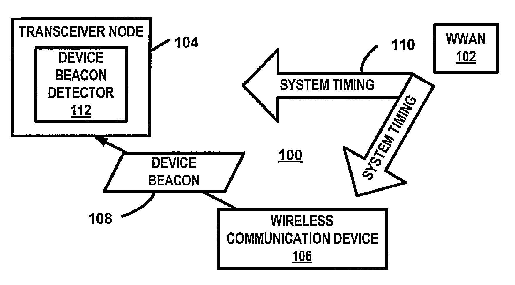
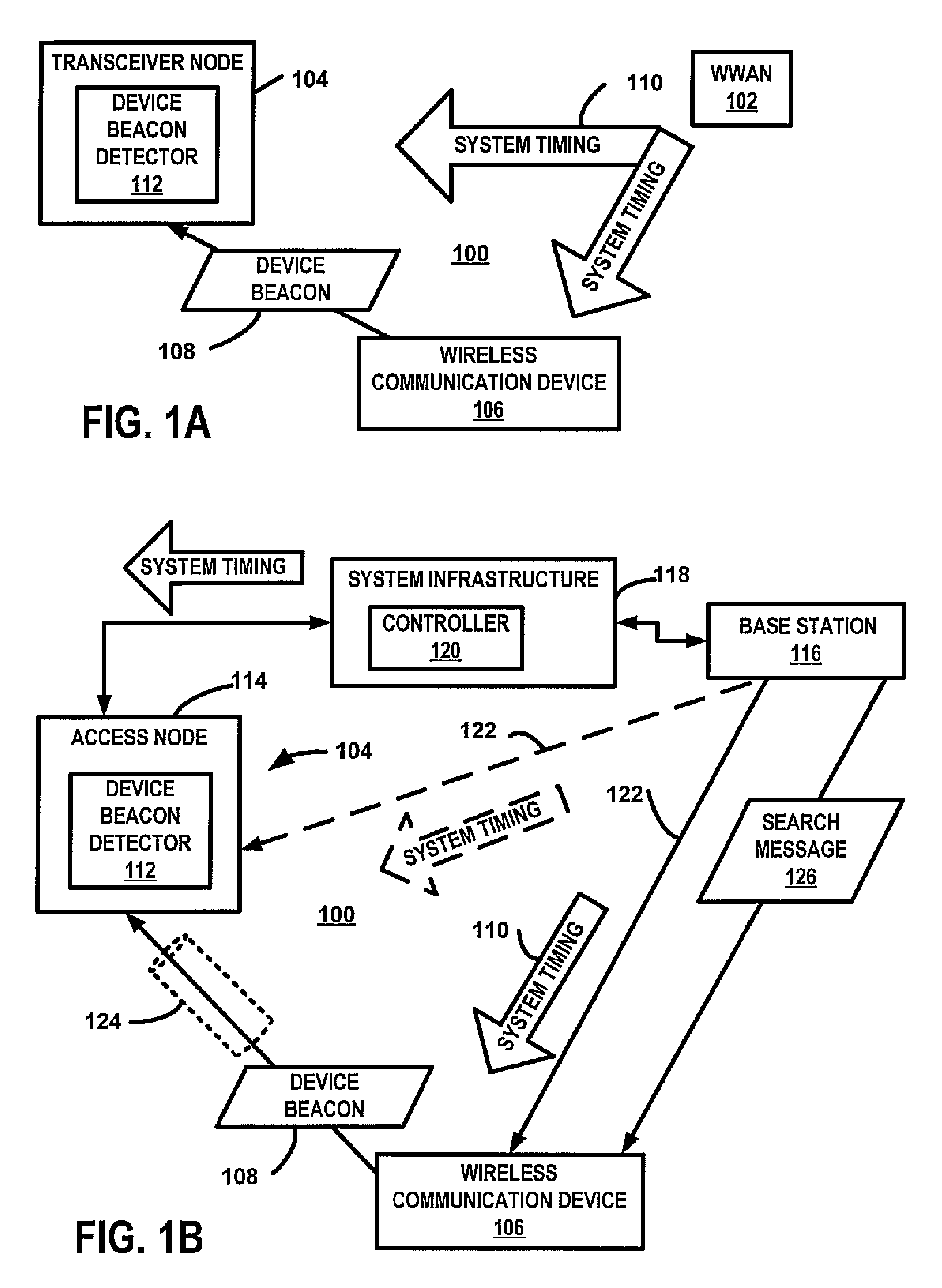
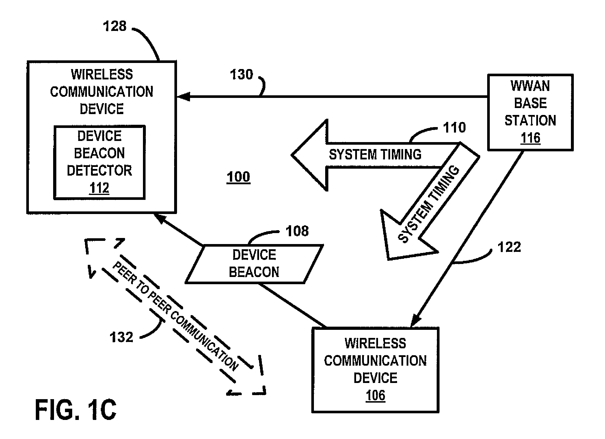
[0029]FIG. 1A is a block diagram of a communication system 100 that includes a wide area wireless network (WWAN) 102, a transceiver node 104, and a wireless communication device 106. The WWAN provides wireless communication services to one or more wireless communication devices 106. The wireless communication device 106, at least periodically, transmits a device beacon 108 in accordance with a system timing 110 of the WWAN 102. The transceiver node 104 also obtains the system timing 110, either wirelessly or through a wired backhaul. A device beacon detector 112 within the transceiver node 104 uses the system timing 110 to monitor device beacon channels and to receive the device beacon 108. As discussed below, the transceiver node 104 may perform any of several tasks in response to detecting the device beacon 108 where at least some of the tasks may result in establishing communications between the transceiver node 104 and the wireless communication device 106.

[0030]The device beaco...


PUM


Abstract

A wireless communication device transmits a device beacon in accordance with a system timing of a wireless wide area network (WWAN). For one example, the beacon is transmitted relative to WWAN uplink channels of the time-frequency space of the uplink WWAN channel assignment. In response to the reception of the device beacon by another wireless communication device, a peer to peer communication session is established.

Description

RELATED APPLICATIONS[0001]This application is related to U.S. patent application entitled “DEVICE BEACON FOR HANDOFF MANAGEMENT OF HANDOFFS TO ACCESS NODES”, Ser. No. ______, docket number TUTL 00179 and to U.S. patent application entitled DEVICE BEACON FOR HANDOFF MANAGEMENT OF HANDOFFS TO BASE STATIONS, Ser. No. ______, docket number TUTL 00170 both filed concurrently with this application and incorporated by reference in their entirety, herein.BACKGROUND[0002]The invention relates in general to wireless communication systems and more specifically to device beacon signals in a wireless communication system.[0003]Wireless communication systems may include base stations or access nodes establish communication links to portable wireless communication devices. In peer to peer communications, the portable wireless communication devices communicate directly to each other without accessing a base station or access node. Conventional systems, however, are limited in that presence of one w...

Claims


Application Information

Patent Timeline
Patent Type & Authority Applications(United States)
IPC IPC(8): H04J3/00
CPCH04W8/005H04W48/08H04L27/2627H04W76/023H04W72/0446H04W72/0453H04W56/001H04W76/14
Inventor KALHAN, AMIT
Owner KYOCERA CORP
Why Eureka
Try Eureka