Intensity-modulated, cone-beam computed tomographic imaging system, methods, and apparatus

a computed tomography and intensity modulation technology, applied in the field of computed tomography, can solve the problems of increasing the risk of cancer, not being implemented, and not being able to shape the window of exposure, so as to reduce the overall radiation exposure

Inactive Publication Date: 2010-05-13
THE METHODIST HOSPITAL RES INST
View PDF18 Cites 49 Cited by
  • Summary
  • Abstract
  • Description
  • Claims
  • Application Information

AI Technical Summary

Benefits of technology

This patent describes new ways to make computerized tomography scans safer by reducing the amount of radiation exposed to patients. These techniques use special light patterns called conical beams that are adjusted based on their strength to focus only on specific areas of concern. This helps minimize harmful side effects while still getting accurate images.

Problems solved by technology

The technical problem addressed by this patent is how to improve the accuracy and safety of computed tomography (CT) scanners by reducing the amount of X-ray radiation that patients receive during diagnostic tests without compromising the quality of the resulting images.

Method used


Image

  • Intensity-modulated, cone-beam computed tomographic imaging system, methods, and apparatus
  • Intensity-modulated, cone-beam computed tomographic imaging system, methods, and apparatus
  • Intensity-modulated, cone-beam computed tomographic imaging system, methods, and apparatus

Examples


example 1

Region of Interest Reconstruction and Dose Reduction Estimation in Collimated CBCT Imaging

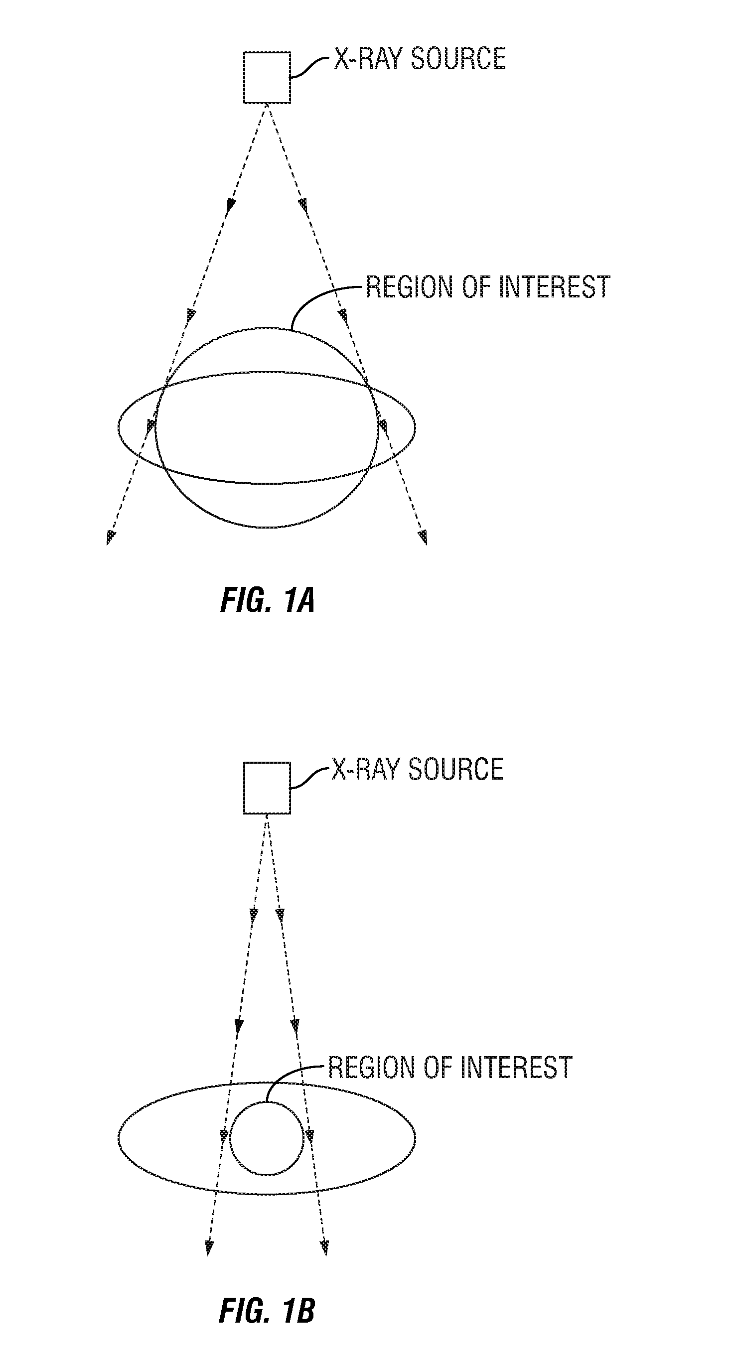
[0057]When objects or bodies extend outside scan FOV, there is abrupt discontinuity at the edges of detector, and projection data is truncated since missing data outside the detector is theoretically assumed to be zero during CBCT reconstruction. In practice, nearly all of the reconstruction algorithms in CBCT scanners are based on the FDK algorithm. Performing one-dimensional (1-D) filtering on truncated projection data leads to bright band artifacts extending inside scan FOV and incorrect reconstruction around the edges of scan FOV7. FIG. 1A shows an example of region of interest (ROI) imaging with mild truncation on projection data commonly encountered due to limitation of detector size. The object is entirely visible at several views, but truncation occurs at the other views. Several analytical reconstruction algorithms8,9 in the backprojection-filtration (BPF) family can exactly reconstruc...


PUM


Abstract

Disclosed are methods for reconstructing a three-dimensional image of an object's volume of interest using computed tomography that employs conical-beam, intensity-modulated projections of this object. In one embodiment, a plurality of collimating devices serves to modulate the aperture of the radiation source thereby acting to modulate the intensity of the source upon the object. Also provided are image processing devices, examination apparatus, as well as a computer-readable medium and a program element adapted and configured to perform aspects of the methods disclosed herein.

Description


Claims


Application Information

Patent Timeline
Owner THE METHODIST HOSPITAL RES INST
Why Eureka
Try Eureka