Modular, brushless motors and applications thereof

a brushless motor and module technology, applied in the field of brushless motors, can solve the problems of inconsequential cost of fan operation and energy cost of component fan parts to be shipped

Inactive Publication Date: 2010-05-13
LAZEBNIK ROBERT +1
View PDF9 Cites 39 Cited by
  • Summary
  • Abstract
  • Description
  • Claims
  • Application Information

AI Technical Summary

Benefits of technology

[0014]According to the invention, the same basic design allows the number of coils, the number of blades, or both, to be varied desired performance requirements. This can be accomplished with the same basic enclosure using the same ring having a fixed ...

Problems solved by technology

In the past, the cost to ship component fan parts and the cos...

Method used


Image

  • Modular, brushless motors and applications thereof
  • Modular, brushless motors and applications thereof
  • Modular, brushless motors and applications thereof

Examples


Embodiment Construction

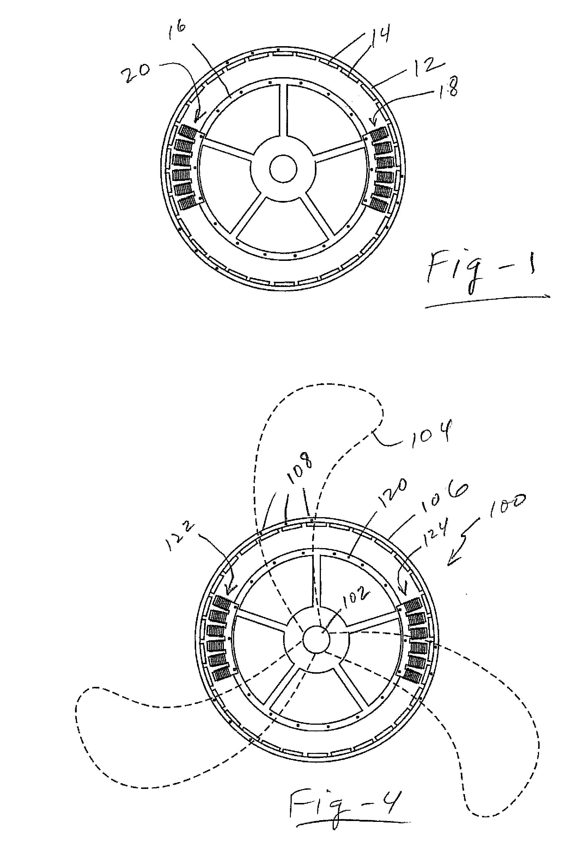
[0020]FIG. 1 is a simplified, front-view drawing of a modular, brushless motor according to the invention. A rotor ring 12 is comprised of a ferromagnetic “back iron” material having inner and outer cylindrical surfaces. The ring 12 is provided with radially oriented permanent magnets 14 on the inner (or outer) surface, magnetized in a circumferentially symmetric, alternating, multi-pole arrangement.

[0021]The stator of the motor includes a number of discrete, individual stator segments, each comprised of electric coils wound on an arrangement of ferromagnetic teeth connected together by a common ferromagnetic flux return yoke structure. The coils are oriented toward and are magnetically coupled to the individual pole magnets of the rotor ring through air gaps established through physical spacing. The windings of the stator segments are connected in a series or parallel arrangement and brought out to a common location where they connect to an electronic speed controller.

[0022]Continu...


PUM


Abstract

A modular brushless motor may be reconfigured for different applications and power levels. As one example, a modular fan enables the drive motor, the number of blades, or both, to be factory adjusted to accommodate different power and air-flow requirements. A brushless ring motor comprises a circular ferromagnetic ring having an inner surface and an outer surface rotatable about a central axis, with a plurality of spaced-apart permanent magnets being bonded to one of the inner surface and outer surfaces of the ring. A stator assembly enables one or more coils to be mounted relative to the permanent magnets enabling a commercially available electronic speed controller to the drive the coils in cooperation with the magnets so as to turn the ring. The stator assembly enables different groups of coils to be mounted relative to the permanent magnets, and the ring is configured to accept different numbers of fan blades. This allows the coils and blades to be mixed and matched to target various performance requirements.

Description

FIELD OF THE INVENTION[0001]This invention relates generally to brushless motors and, in particular, to modular configurations that may be used in air circulators and other applications.BACKGROUND OF THE INVENTION[0002]There are three main types of fans used for moving air: axial, centrifugal (also called radial) and cross flow (also called tangential). Axial fans have blades that force air to move parallel to the shaft about which the blades rotate. This type of fan is used in a wide variety of applications, ranging from small cooling fans to giant fans used in wind tunnels.[0003]Most residential and industrial axial fans use a motor having a shaft to which the blades are connected. This has been convenient in terms of manufacture, since component parts, including motors, could come from different sources to optimize a design.[0004]In the past, the cost to ship component fan parts and the cost of energy required for fan operation were largely inconsequential. Today, however, with r...

Claims


Application Information

Patent Timeline
IPC IPC(8): F04D25/06H02K21/12
CPCF04D27/004H02K7/14H02K21/225F04D25/0646F04D25/064F04D25/0633H02K41/03Y02B30/70
Inventor LAZEBNIK, ROBERTMCCLEER, PATRICK J.
Owner LAZEBNIK ROBERT
Why Eureka
Try Eureka