Mobile communication system and communication method

Inactive Publication Date: 2010-05-13
NEC CORP
View PDF6 Cites 14 Cited by
  • Summary
  • Abstract
  • Description
  • Claims
  • Application Information

AI Technical Summary

Benefits of technology

[0024]Consequently, it is an object of the present invention to solve the abovementioned problems, and to provide a mobile communication system (and in particular, a base station therefor) in which information on the number of packets (that is, data volume) counted up to now at a base station of a mobile source can be transferred to a base station of a mobile target even when a terminal performs a handover.
[0028]In this way, in the mobile communication system of the present invention, it is possible for information on the number of packets counted up until then by the eNode B to be transferred to the Target eNode B where the UE is moving to, even if the UE is undergoing handover between eNode Bs. That is, in the mobile communication system of the present invention, for example, after termination of UE communication, it becomes possible to accurately report the number of packets counted by the eNode B to the CN Node, and since the CN Node can report to a charging center, it becomes possible to have accurate charging.
[0029]Furthermore, in the mobile communication system of the present invention, even if the CN Node is switched due to a handover, by providing notification of information of the number of packets counted up until then from the switching source CN Node to a switching target, since it is possible to report information on the number of communicated packets of the UE to the charging center, it becomes possible to have accurate charging. Various aspects of the invention are described below.
[0034]In the present invention, by the abovementioned configuration and operation, an effect is obtained in which, even when a terminal performs a handover, it is possible for information on the number of packets counted up until then at a base station of a mobile source to be transferred to a base station of a mobile target.

Problems solved by technology

With regard to this LTE handover method, since a disconnect signal from a CN Node to a Source eNode B does not exist, there is a problem in that the amount counted by the Source eNode B cannot be reported to the CN Node.
This problem causes a further problem in that, since the Source eNode B cannot report the number of packets successfully received before a UE handover to the CN Node, it is not possible to accurately charge for the number of packets successfully received before the UE handover.

Method used


Image

  • Mobile communication system and communication method
  • Mobile communication system and communication method
  • Mobile communication system and communication method

Examples


exemplary embodiment 1

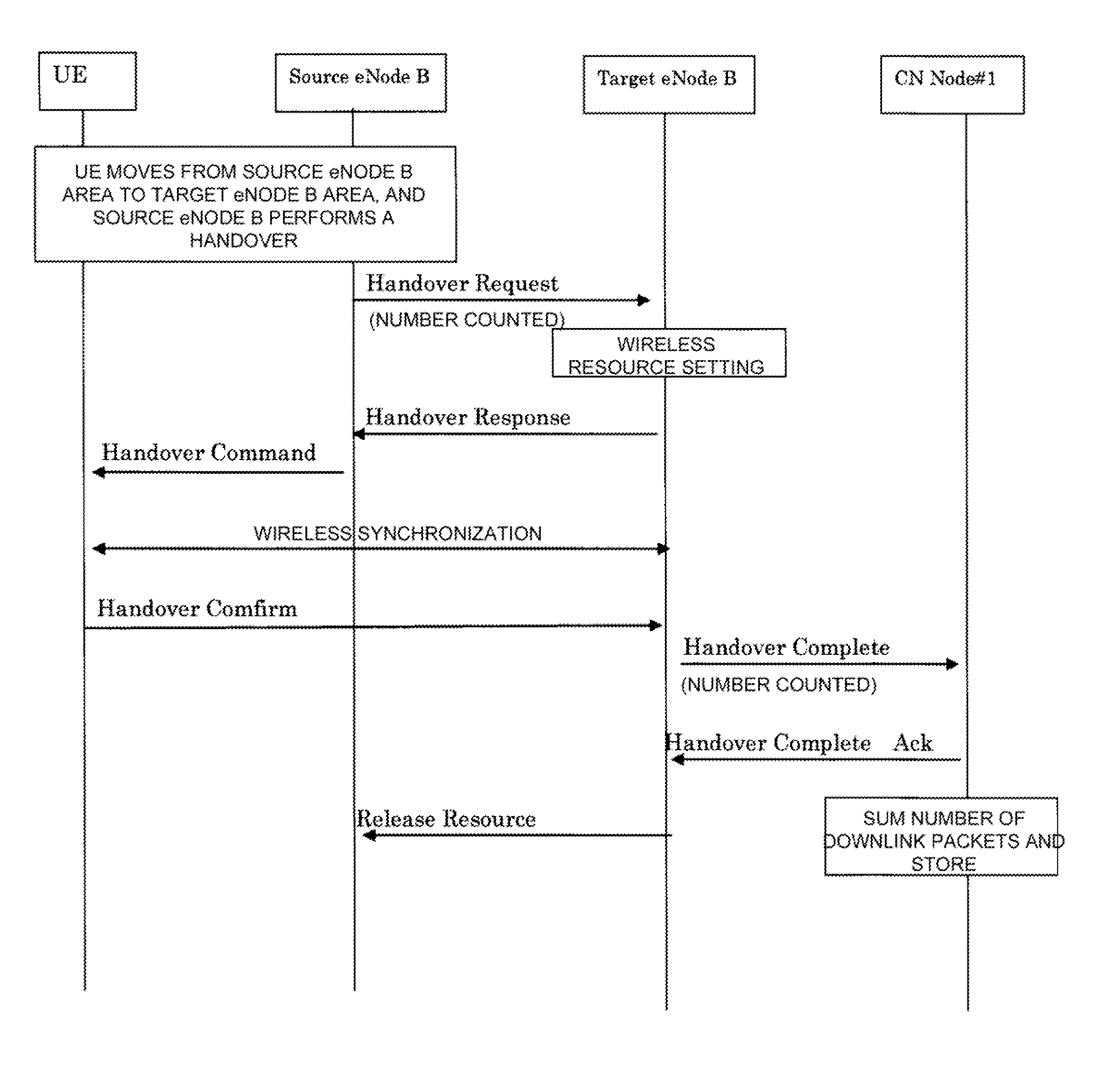
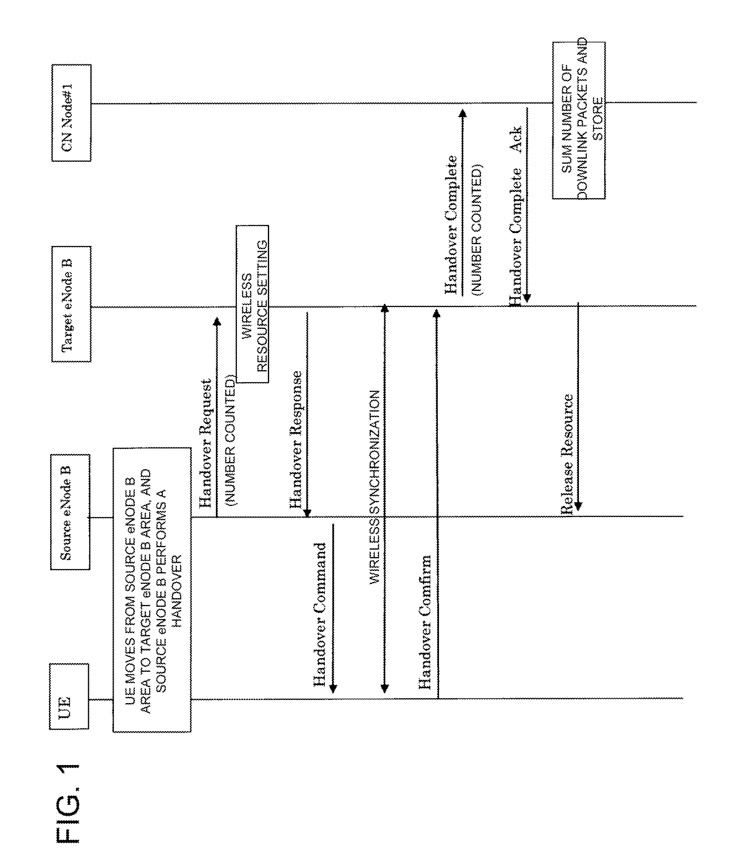
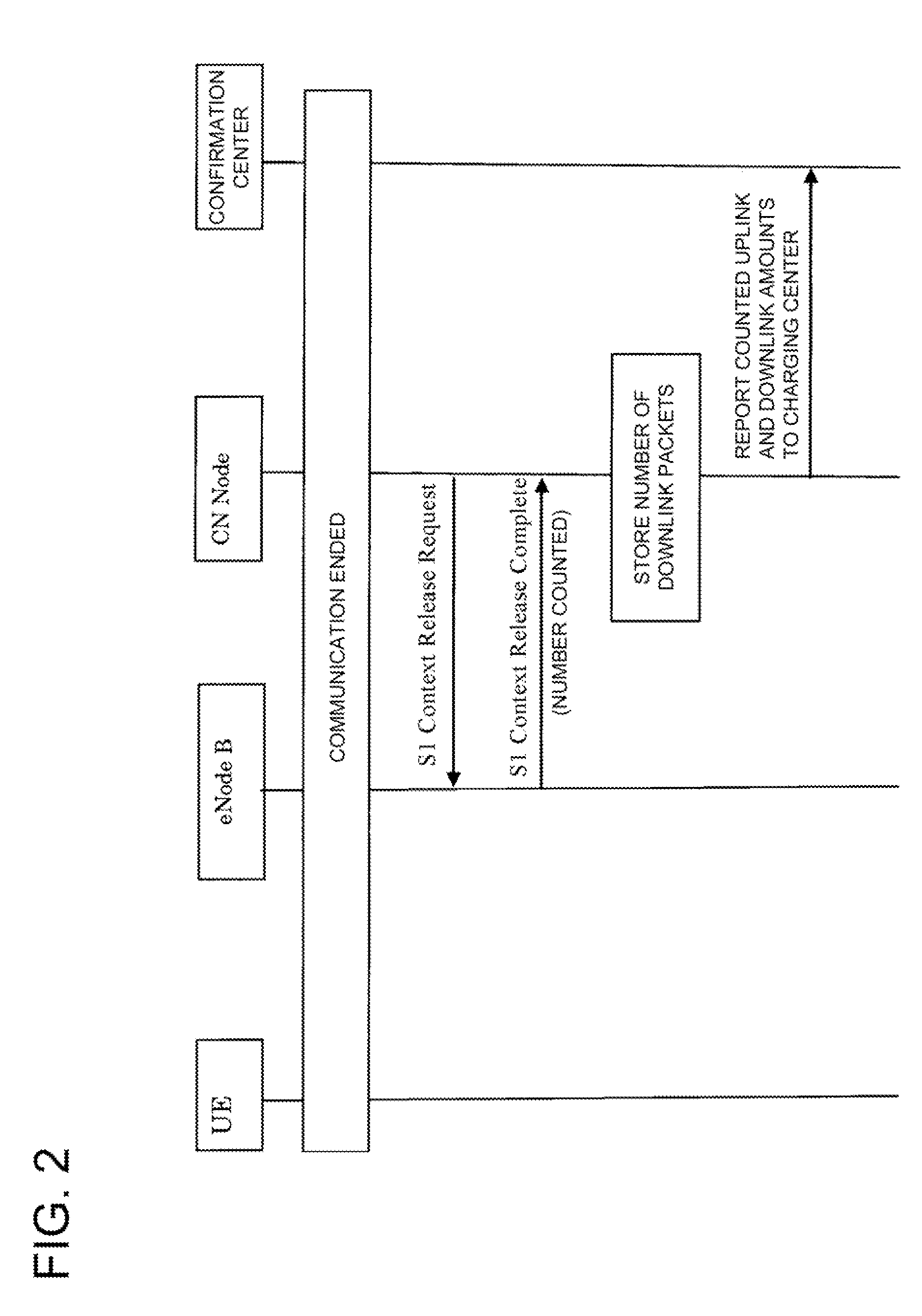
[0059]FIG. 1 is a sequence chart showing a handover procedure of a mobile communication system according to a first exemplary embodiment of the present invention; FIG. 2 is a sequence chart showing a procedure of reporting information counted according to the first exemplary embodiment of the invention; and FIG. 3 is a drawing showing information (data volume report) of the number of packets reported in the first exemplary embodiment of the present invention. Making reference to FIGS. 1 to 3, a description is given concerning operation of the mobile communication system according to the first exemplary embodiment of the present invention.

[0060]In the description below, the mobile communication system according to the first exemplary embodiment of the present invention is configured from the respective devices:

[0061]Source eNode B=mobile source base station

[0062]Target eNode B=mobile target base station

[0063]UE (User Equipment)=wireless terminal, also referred to simply as terminal, ...

exemplary embodiment 2

[0073]FIG. 4 is a sequence chart showing a handover procedure of the mobile communication system according to a second exemplary embodiment of the present invention. With regard to FIG. 4, in the present exemplary embodiment, a Release Resource Complete message is provided from a Source eNode B to a Target eNode B, and information on the number of packets counted by the Source eNode B before handover is included in the Release Resource Complete message and transmitted.

[0074]In the present exemplary embodiment, for example, in a case where the handover procedure has been unsuccessful due to the Target eNode B failing to capture a resource or the like, it is possible to eliminate needless information transfer by a handover request message from the Source eNode B.

[0075]Furthermore, timing of reporting the number of packets counted from the eNode B to the CN Node, as shown in FIG. 2, for example, accompanying UE communication completion, in order to release a resource to the eNode B, th...

exemplary embodiment 3

[0078]FIG. 5 is a sequence chart showing a procedure of reporting information counted according to a third exemplary embodiment of the present invention. Making reference to FIG. 5, a description is given of the procedure of reporting information counted according to the third exemplary embodiment of the present invention.

[0079]As shown in FIG. 5, after carrying out a handover, if a Source eNode B receives a Release Resource from a Target eNode B, information on the number of packets counted up until then is reported to a CN Node by a Release Resource Indication message, and information on the number of packets thus counted is summed with the number of packets counted by the CN Node up until then, and stored in memory.

[0080]Thereafter, the CN Node reporting to a charging center involves, for example, accompanying UE communication completion, in FIG. 2, reporting the number of packets counted, which have been received up until then by the CN Node, to the charging center.

[0081]In this...


PUM


Abstract

A wireless communication system comprises a first base station, a second base station, and a wireless terminal. The wireless terminal performs a handover from the first base station to the second base station. The first base station transmits information related to data volume of downlink data to the second base station, when the handover is performed. The second base station receives information related to the data volume.

Description

[0001]This application is the National Phase of PCT / JP2008 / 055274, filed Mar. 21, 2008, which is based upon and claims the benefit of the priority of Japanese patent application No. 2007-074554, filed on Mar. 22, 2007, the disclosure of which is incorporated herein in its entirety by reference thereto.FIELD OF THE INVENTION[0002]The present invention relates to a mobile communication system and base station thereof, and in particular to information relating to the number of packets (namely, data volume) at handover in the mobile communication system.BACKGROUND OF THE INVENTION [0003]A mobile communication system in 3GPP (3rd Generation Partnership Project) LTE (Long Term Evolution) aims for an architecture as shown in FIG. 7. It is an object of this architecture to build a system that can realize shortening of transmission delay in a control plane and a user plane, and in which data transfer with higher throughput, for example, than existing systems can be realized.[0004]An operator...

Claims


Application Information

Patent Timeline
IPC IPC(8): H04W36/08H04L12/70H04M1/725H04W4/24H04W36/00H04W36/02H04W92/20
CPCH04L12/14H04L12/1435H04M15/73H04M15/8038H04M2215/204H04W92/20H04M2215/7442H04W4/24H04W4/26H04W36/0055H04W36/02H04M2215/7072H04W36/08H04W36/0072H04W88/02H04W88/08H04W72/23
Inventor HAYASHI, SADAFUKU
Owner NEC CORP
Why Eureka
Try Eureka