Industrial machine

a construction machine and machine body technology, applied in the field of industrial machines, can solve the problems of insufficient accuracy of tilt sensor response, high cost of position detecting system including gps antenna, and high cost of system, so as to improve the accuracy of detecting the center position of the target, and achieve the effect of easy extraction, accurate detection and improved accuracy

Active Publication Date: 2010-05-13
KK TOPCON
View PDF8 Cites 49 Cited by
  • Summary
  • Abstract
  • Description
  • Claims
  • Application Information

AI Technical Summary

Benefits of technology

The present invention describes an industrial machine equipped with cameras and a computer program that uses these cameras to track the positions of objects attached to the machinery. This allows for accurate detection of the position and posture of the machines' work implements, which enables precise control over their operations. Additionally, this technology does not require costly equipment or delays in responding to changes in the machine's condition.

Problems solved by technology

The technical problem addressed in this patent is how to accurately determine the position and posture of a construction machine's working implement, particularly its blade or soil-pushing blade, with respect to the main machine frame during use. This is important because current methods rely on sensors that have limited precision and may produce incorrect results due to movement or vibration.

Method used


Image

  • Industrial machine
  • Industrial machine
  • Industrial machine

Examples


Embodiment Construction

[0026]A description will be given below on the best mode for carrying out the present invention by referring to the attached drawings.

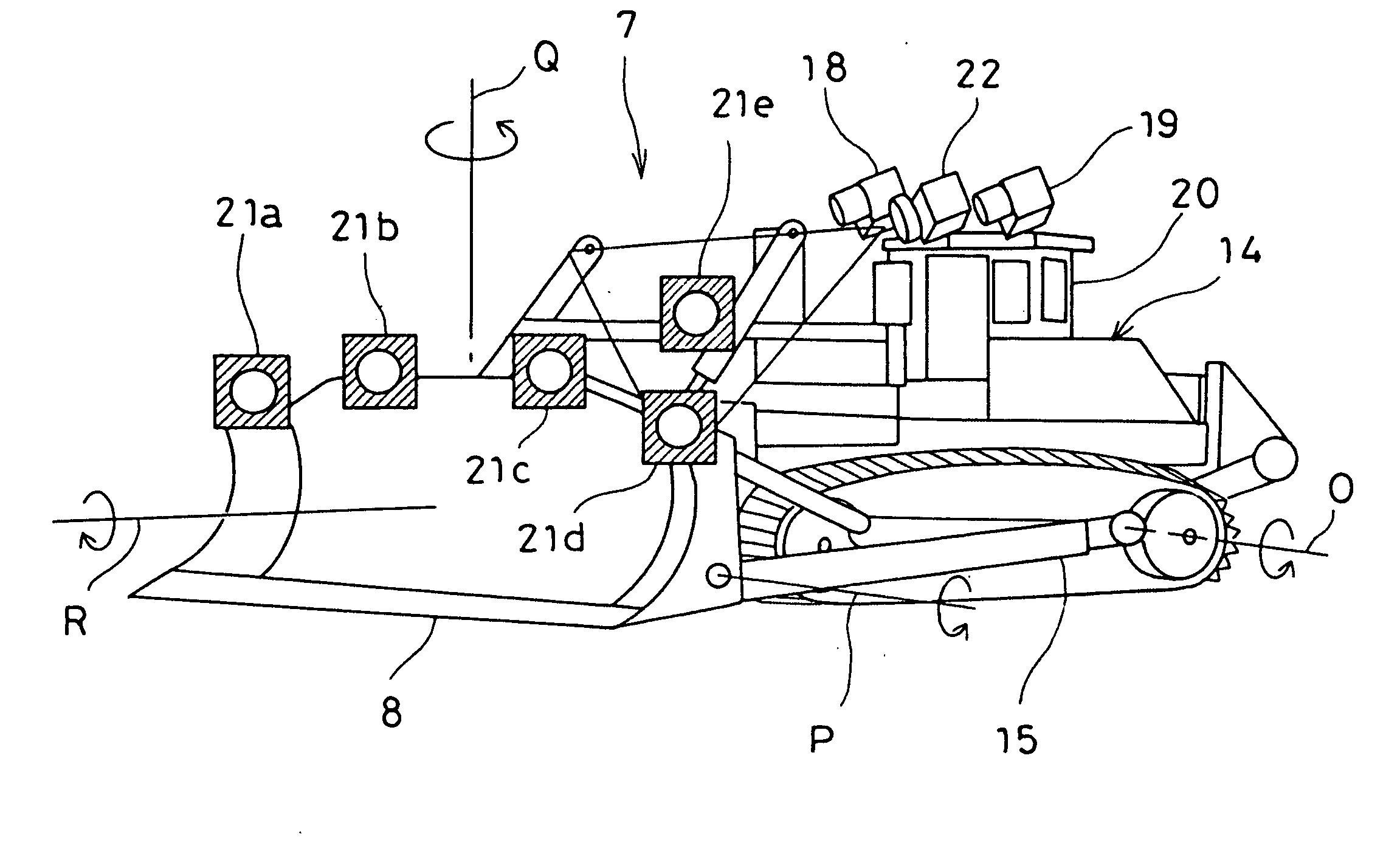
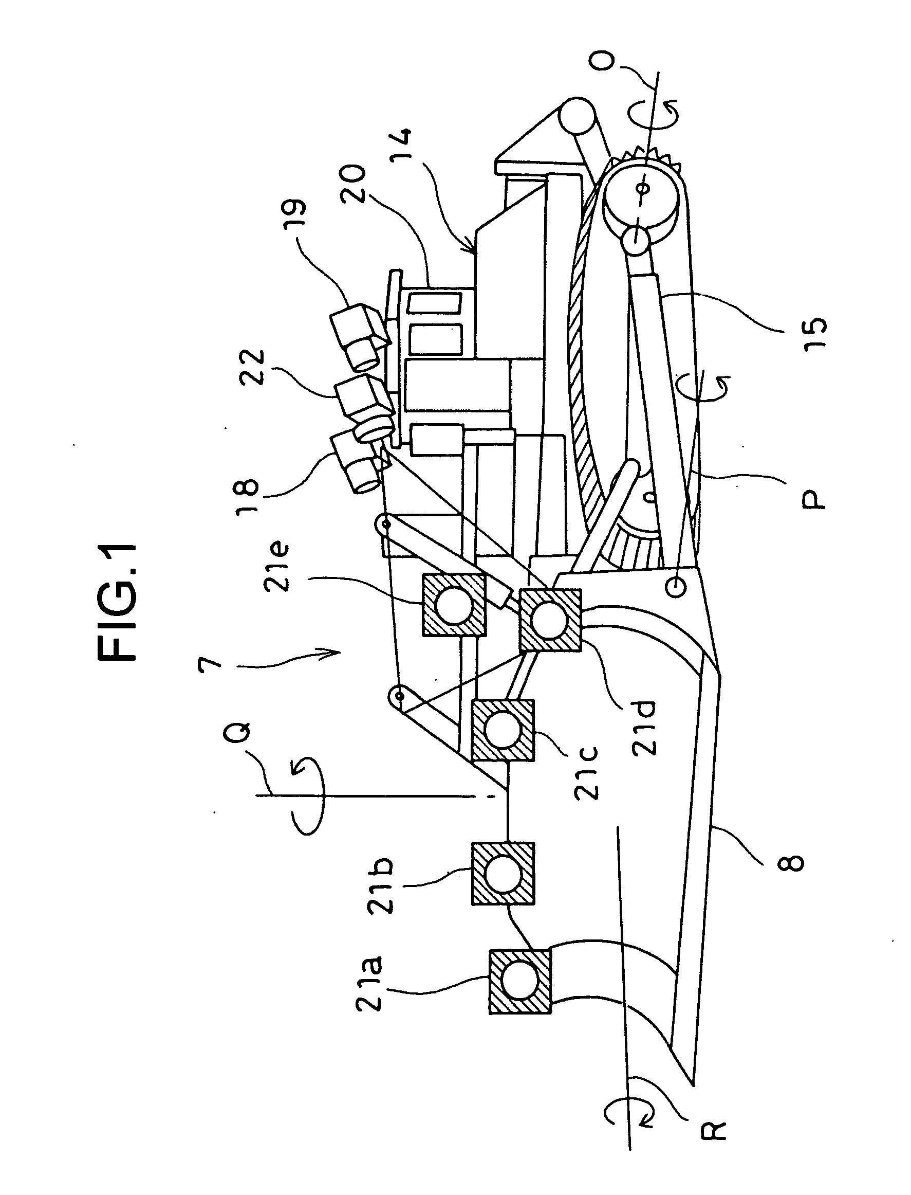
[0027]First, referring to FIG. 1, a description will be given on an example of a construction machine, in which the present invention is carried out.

[0028]In FIG. 1, a bulldozer 7 is shown as a construction machine, and the bulldozer 7 is provided with a bulldozer blade 8 mounted on its front surface as a construction working implement. The blade 8 is disposed at a forward end of an arm 15, which is attached on a bulldozer main unit 14. The blade 8 is so designed that the blade 8 can be rotated in directions along four axes with respect to the bulldozer 7 so that the blade 8 can have various types of postures to match a multi-functional purposes.

[0029]The arm 15 is mounted on the bulldozer main unit 14 so that the arm 15 can be tilted around an O-axis which runs in horizontal direction with respect to the bulldozer main unit 14. The blade 8 is mounted...


PUM


Abstract

The present invention provides an industrial machine, which comprises an industrial machine main unit 14, a construction working implement 8 installed on the industrial machine main unit, two cameras 18 and 19 each mounted at a known position with respect to a machine center of the industrial machine main unit, at least three targets 21 being installed on the working implement so that the targets are within visual field of each of the two cameras, and an arithmetic processing device 23 for extracting the images of at least three targets in common to the images from stereo-images taken by the two cameras, for obtaining a three-dimensional position of each target image, and for calculating a position and a posture of the working implement with respect to the industrial machine main unit based on the three-dimensional position obtained.

Description


Claims


Application Information

Patent Timeline
Owner KK TOPCON
Why Eureka
Try Eureka