Method of designing a composite laminate

a composite laminate and design technology, applied in the field of composite laminate design, can solve the problems of significant changes in bending stiffness driven behaviours like buckling, methods that do not permit optimisation of conventional methods that do not optimise the stacking sequence of the laminate, etc., to achieve sufficient buckling capability and sufficient strength

Inactive Publication Date: 2010-05-13
AIRBUS OPERATIONS LTD
View PDF9 Cites 55 Cited by
  • Summary
  • Abstract
  • Description
  • Claims
  • Application Information

AI Technical Summary

Benefits of technology

[0010]Preferably the optimisation process is a gradient-based optimisation process which performs repeated structural analysis, sensitivity analysis and mathematical optimisation steps and seeks to identify a set of sub-ply selection variables and local laminate thicknesses which optimise an objective function whilst satisfying one or more constraint requirements. Each analysis step calculates current values for the objective functions and one or more constraint functions based on a current set of sub-ply selection variables and local laminate thicknesses, each sensitivity analysis step determines partial derivatives of the output of the structural analysis, and each mathematical optimisation step solves an approximate optimisation problem to determine improved values for the sub-ply selection variables and local laminate thicknesses which optimise the objective function whilst ensuring that each constraint function complies with an associated constraint requirement.
[0011]By way of example, the structural analysis may involve a calculation of buckling and strength measures, and the constraint requirements could require these strength and buckling measures to be above certain limits. This would ensure design of a laminate having sufficient buckling capability and sufficient strength.

Problems solved by technology

However, conventional methods do not optimise the laminate's stacking sequence (that is, the sequence of ply orientation angles through the stack) and simplistic assumptions are made about the laminates bending stiffness.
This may, when converting the continuous design description into a discrete laminate stacking sequence, lead to significant changes in bending stiffness driven behaviours like buckling.
However, such methods do not permit optimisation of the laminate's stacking sequence, which is predefined by the stacking sequence table.
A first disadvantage with this approach is that it formulates an optimisation problem with far too many design variables.
A second disadvantage is that it does not achieve ply continuity between adjacent zones.

Method used


Image

  • Method of designing a composite laminate
  • Method of designing a composite laminate
  • Method of designing a composite laminate

Examples


Embodiment Construction

)

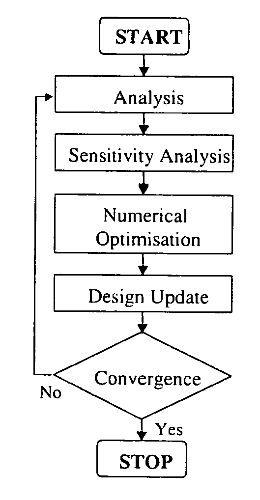
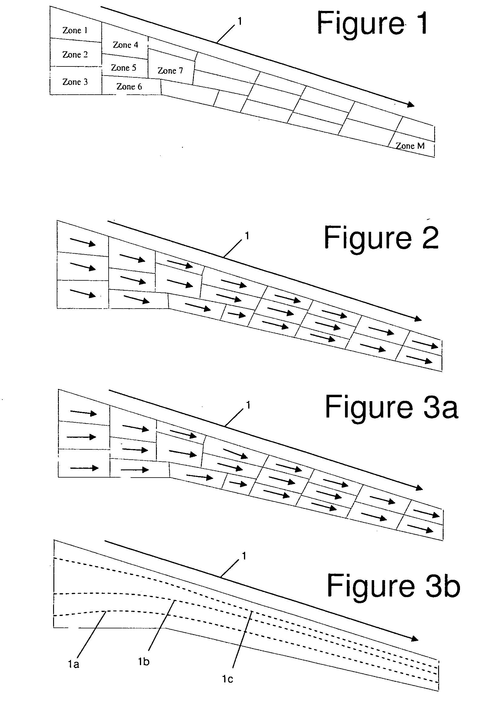
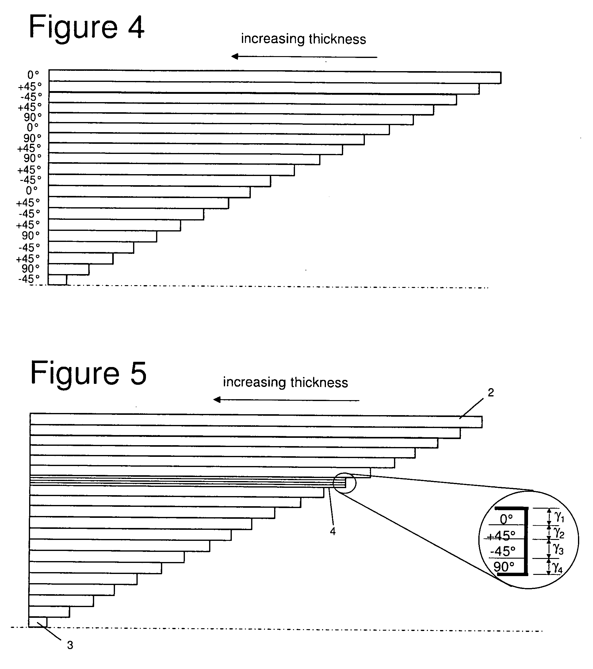
[0028]We describe below a method of designing a composite laminate. The method uses an optimisation design description that allows simultaneous design of a laminate's thickness, constitution, ply orientations and stacking sequence in a single continuous process of optimisation. The optimisation design description introduces a number of global and local design variables in order to achieve a laminate description that utilises the laminate's design freedom whilst ensuring ply continuity across the structure, keeping the optimisation problem size and computational efforts at a manageable size. It is noted that the term “laminate constitution” is used herein to describe the percentages of the various ply orientations. For instance a laminate may be said to have a constitution of 30% 0° plies, 30%+ / −45° plies, and 30% 90° plies. When designing a laminate both the laminate's in-plane properties (for instance in-plane stiffness) and out-of-plane properties (for instance bending and torsio...


PUM


Abstract

A method of designing a composite laminate, the laminate comprising a plurality of zones, each zone comprising a plurality of plies of composite material, each ply in each zone having a respective ply orientation angle. A global stacking sequence is determined for the laminate, the global stacking sequence comprising a sequence of stacking sequence elements. A local laminate thickness is determined for each zone. A local stacking sequence is then determined for each zone by extracting a subsequence of stacking sequence elements from the global stacking sequence. The global stacking sequence and the local laminate thicknesses are determined together in an optimisation process in which multiple sub-ply selection variables are assigned to each stacking sequence element, each sub-ply selection variable representing the density or sub-ply thickness for a respective candidate ply orientation angle. Optimal values are determined for the sub-ply selection variables and the local laminate thicknesses. A single one of the sub-ply selection variables is assigned to each stacking sequence element thereby forcing a discrete choice of global ply orientation angle for each stacking sequence element.

Description

FIELD OF THE INVENTION[0001]The present invention relates to a method of designing a composite laminate, the laminate comprising a plurality of zones, each zone comprising a plurality of plies of composite material, each ply in each zone having a respective ply orientation angle.BACKGROUND OF THE INVENTION[0002]Continuous approaches to optimisation of composite laminates allow optimisation of a laminate's in-plane stiffness by optimising the laminate thickness, the percentages of plies oriented along different directions, and the directions of these plies. However, conventional methods do not optimise the laminate's stacking sequence (that is, the sequence of ply orientation angles through the stack) and simplistic assumptions are made about the laminates bending stiffness. This may, when converting the continuous design description into a discrete laminate stacking sequence, lead to significant changes in bending stiffness driven behaviours like buckling. Also additional weight cou...

Claims


Application Information

Patent Timeline
Patent Type & Authority Applications(United States)
IPC IPC(8): G06F17/50G06G7/48
CPCG06F17/5004G06F2217/44G06F2217/08G06F30/13G06F2111/06G06F2113/26
Inventor KROG, LARS
Owner AIRBUS OPERATIONS LTD
Why Eureka
Try Eureka