
Valve driving apparatus

a technology of driving apparatus and valve, which is applied in the direction of valve details, valve arrangement, valve drive, etc., can solve the problems of insufficient time and degree of valve opening, disadvantageous idle stability and low-speed torque characteristics under low-speed conditions, and limited performance under high-speed conditions, so as to achieve optimal fuel economy and output

Inactive Publication Date: 2010-05-20
GARGASO ENG
View PDF1 Cites 8 Cited by
  • Summary
  • Abstract
  • Description
  • Claims
  • Application Information

AI Technical Summary

Benefits of technology

[0010]The present invention is conceived to solve the above problems of the related art, and an aspect of the invention is to provide a valve driving apparatus that is capable of precisely adjusting lift amounts of valves periodically opening and closing a combustion chamber of an internal combustion engine with a double-cam unit associated therewith in order to achieve optimum fuel economy and output.

Problems solved by technology

Thus, with a design contemplated for low speed driving conditions, time and degree of valve opening are insufficient in high-speed drive conditions, and with a design contemplated for the high speed drive conditions, a reverse phenomenon occurs in the low speed drive conditions.
More specifically, since a general internal combustion engine tuned for high speed driving is set to have a high valve lift value, it exhibits good performance under high-speed conditions, but is very disadvantageous in terms of idle stability and low-speed torque characteristics under low speed conditions.
On the contrary, the engine tuned for low speed driving provides good idle stability and low-speed torque under low-speed conditions but exhibits limited performance under high-speed conditions.
In a conventional variable valve lift-type valve driving apparatus, however, since the lift amount of the valve cannot be varied and time of opening or closing the intake or exhaust valve is fixed in a constant state, the amount of intake or exhaust air cannot be adjusted, so that optimum fuel economy and output cannot be obtained corresponding to an engine operation state.

Method used


Image

  • Valve driving apparatus
  • Valve driving apparatus
  • Valve driving apparatus

Examples


Embodiment Construction

[0027]Embodiments of the invention will now be described in detail with reference to the accompanying drawings. It should be noted that the drawings are not to precise scale and may be exaggerated in thickness of lines or sizes of components for descriptive convenience and clarity only. Furthermore, the terms as used herein are defined by taking functions of the invention into account and can be changed according to the custom or intention of users or operators. Therefore, definition of the terms should be made according to the overall disclosures set forth herein.

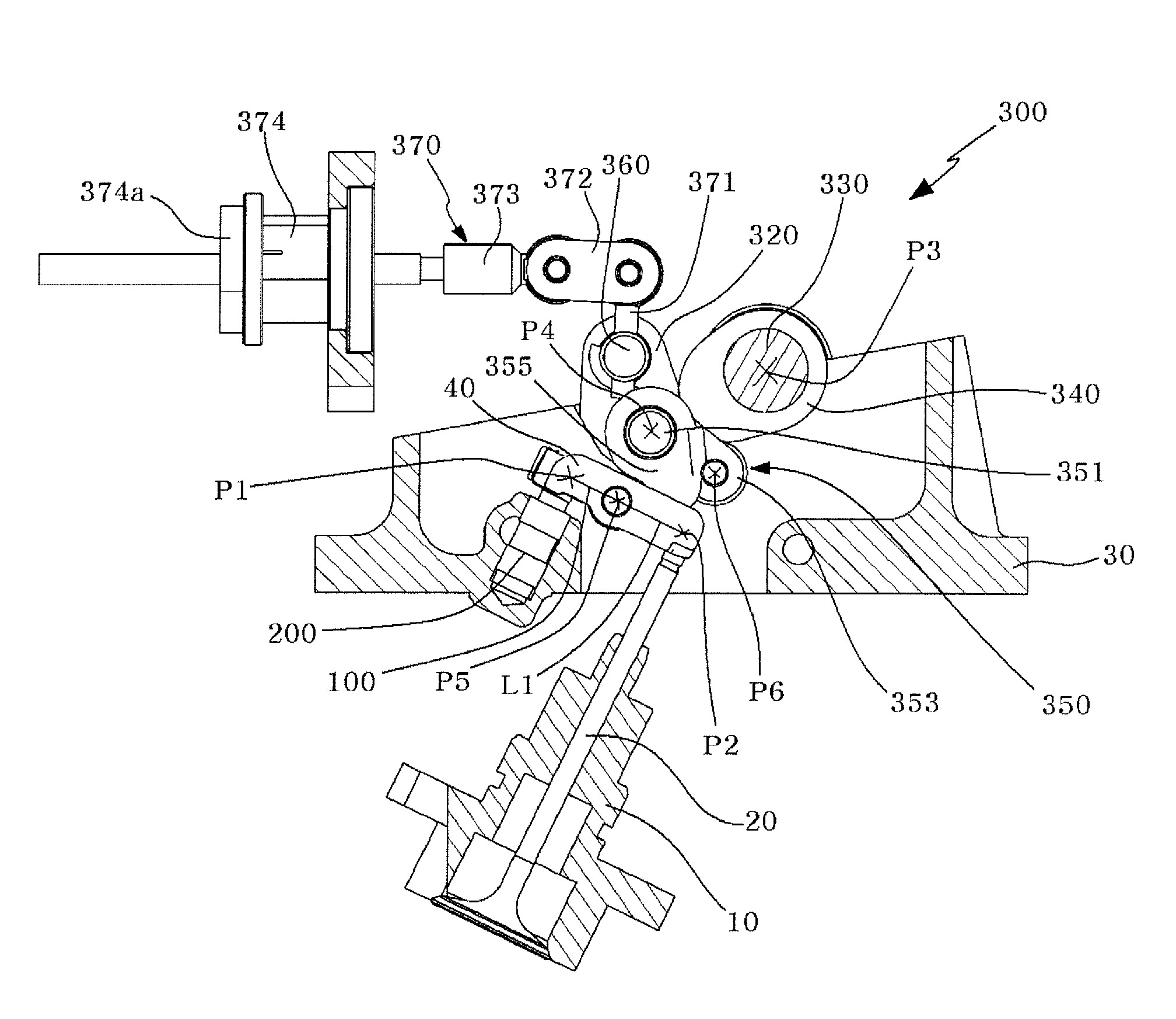
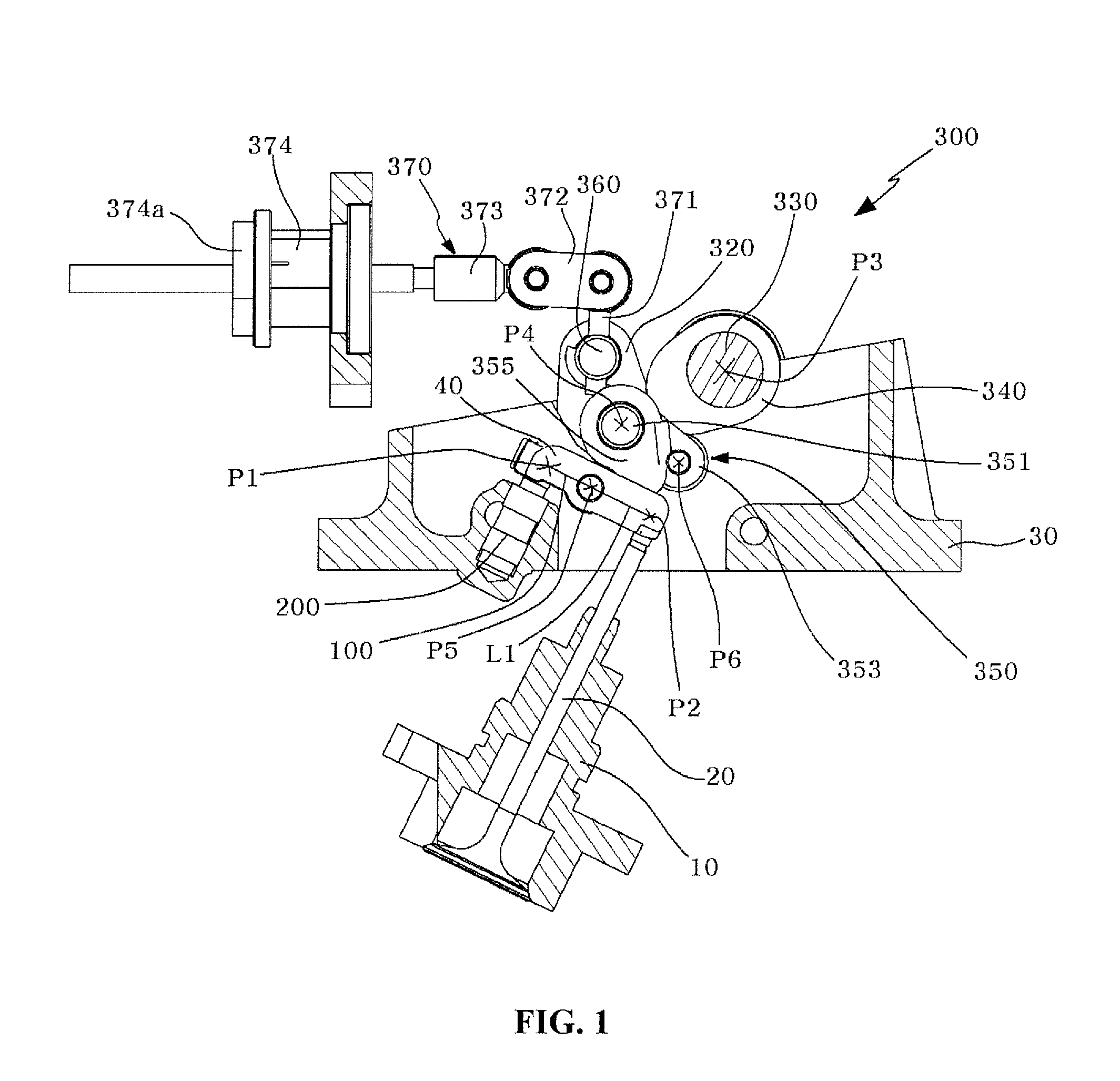
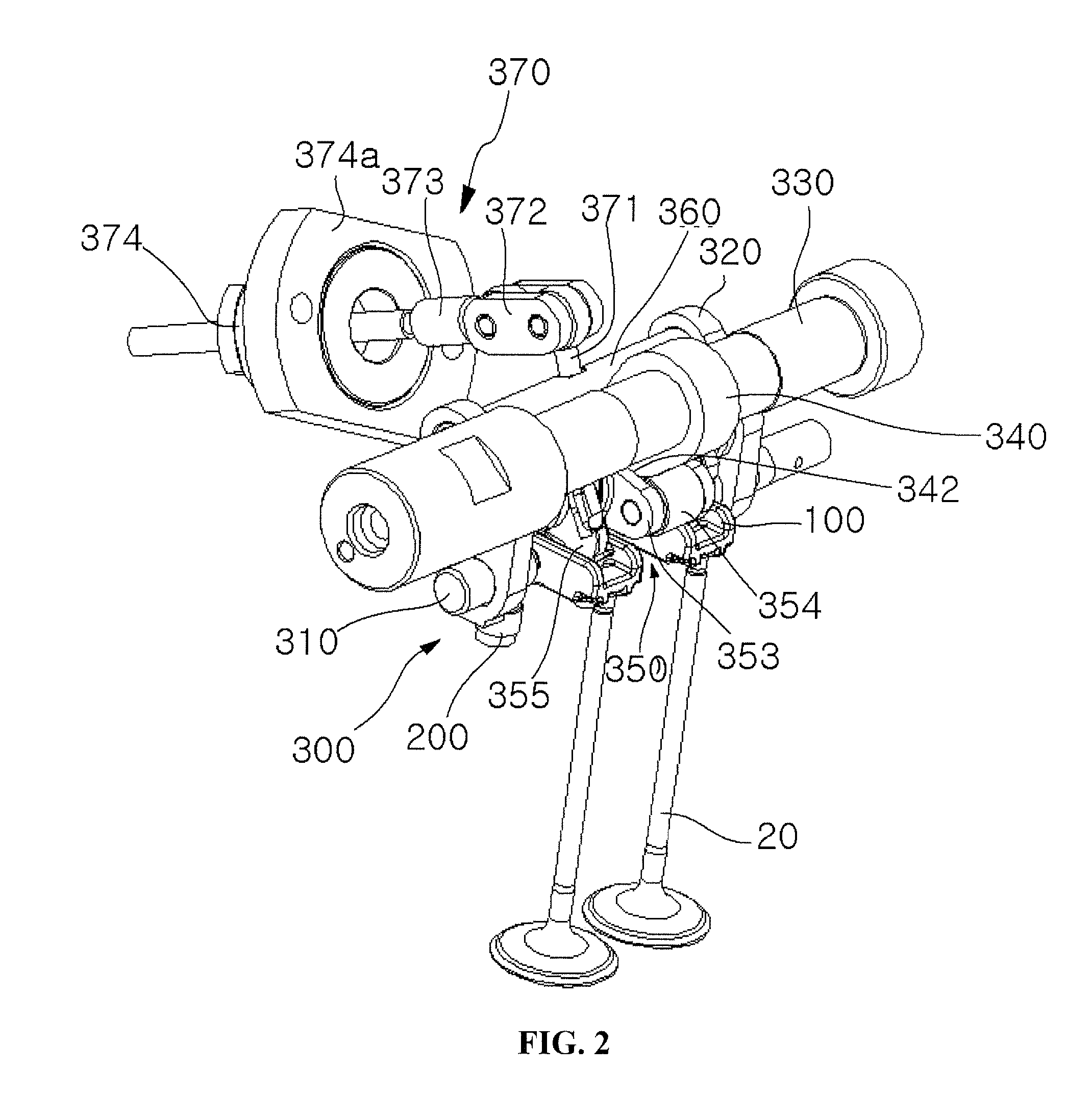
[0028]Referring to FIGS. 1 to 4, a valve driving apparatus according to one embodiment of the invention includes swing arms 100 and a cam unit 300, which can variably control lift amounts of valves 20 opening and closing a combustion chamber 10 in an internal combustion engine.

[0029]Each of the swing arms 100 has one side corresponding to an upper side of the valve 20, which opens and closes the combustion chamber 10, and ...


PUM


Abstract

Disclosed herein is a valve driving apparatus. The valve driving apparatus includes at least one swing arm having one side corresponding to an upper side of a valve opening and closing a combustion chamber of an internal combustion engine; and a cam unit periodically pivoting the swing arm. Here, the swing arm performs a swing motion on the other side thereof by external manipulation to periodically compress the valve. The valve driving apparatus is capable of adjusting lift amounts of valves opening and closing a combustion chamber of an internal combustion engine.

Description

CROSS-REFERENCE TO RELATED APPLICATION[0001]This application claims the benefit under 35 U.S.C. §119 of Korean Patent Application No. 10-2008-0113562, filed Nov. 14, 2008, which is hereby incorporated by reference in its entirety.BACKGROUND OF THE INVENTION[0002]1. Field of the Invention[0003]The present invention relates to a valve driving apparatus and, more particularly, to a valve driving apparatus that is capable of continuously adjusting lift amounts of valves opening and closing a combustion chamber of an internal combustion engine with a double-cam unit to provide optimum fuel economy and output.[0004]2. Description of the Related Art[0005]In general, an internal combustion engine of vehicles includes a combustion chamber in which fuel is burned to generate power. The combustion chamber is provided with a valve train, which includes intake / exhaust valves controlling the flow of intake and exhaust gases and is associated with a crankshaft to open and close the combustion cham...

Claims


Application Information

Patent Timeline
IPC IPC(8): F01L1/34
CPCF01L13/0021F01L2820/032F01L2013/0068F01L13/0026F01L13/00F01L1/18F01L1/04
Inventor KIM, HYUNG GI
Owner GARGASO ENG
Learn More