Apparatus and Method for Depositing a Slurry in a Well

a technology of slurry and well, which is applied in the direction of fluid removal, earth drilling and mining, and well accessories. it can solve the problems of large equipment footprint, significant problems, and costly and dangerous equipment failures

Active Publication Date: 2010-05-20
PICOU ROBERT A
View PDF9 Cites 24 Cited by
  • Summary
  • Abstract
  • Description
  • Claims
  • Application Information

AI Technical Summary

Benefits of technology

[0005]It is an object of the present inventio

Problems solved by technology

Those of ordinary skill in the art will appreciate that the production of reservoir sand can lead to significant problems including costly and dangerous equipment failure.
Gravel packing with jointed pipe and coiled tubing require the use of specialized deployment mechanisms such a

Method used


Image

  • Apparatus and Method for Depositing a Slurry in a Well
  • Apparatus and Method for Depositing a Slurry in a Well
  • Apparatus and Method for Depositing a Slurry in a Well

Examples


Embodiment Construction

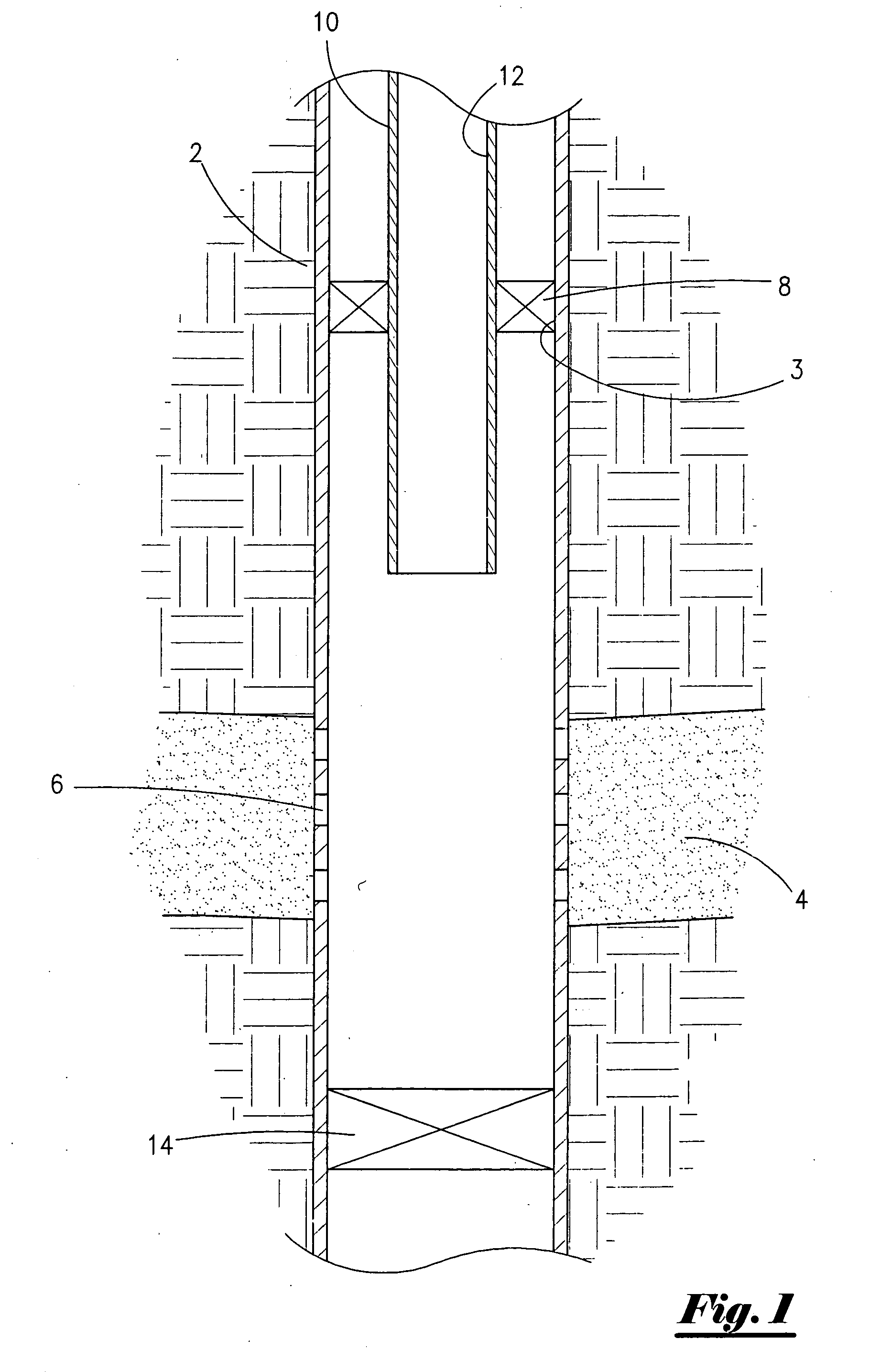
[0050]With reference to the figures where like elements have been given like numerical designation to facilitate an understanding of the present invention, and with reference to FIG. 1, well 2 has been completed to subterranean reservoir 4. Well 2 has perforations 6 for allowing passage of reservoir fluids and gas as well understood by those of ordinary skill in the art. Production packer 8 is sealingly engaged with inner portion 3 of well 2. Production packer 8 has tubing string 10 operatively attached. Tubing string 10 has internal bore 12 (also referred to as internal portion 12). Bottom plug 14 is also shown.

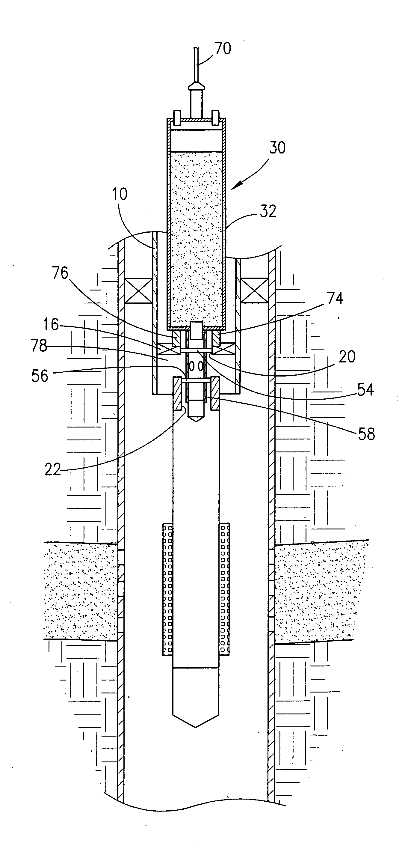
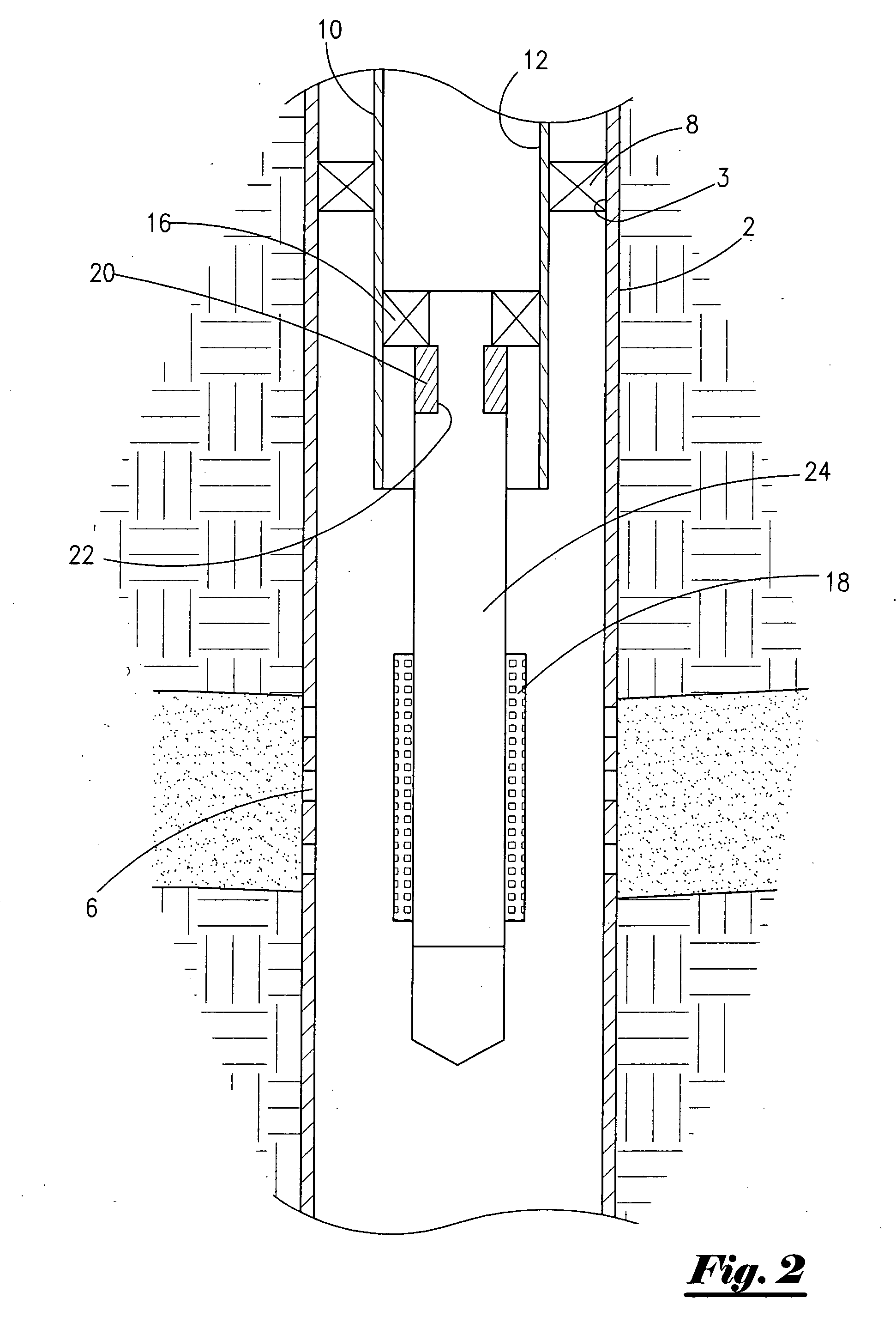
[0051]FIG. 2 is a schematic illustration of well 2 seen in FIG. 1 with an attached gravel-pack packer 16 and gravel pack screen 18. Gravel-pack packer 16 is attached to inner bore 12 of tubing 10 and includes gravel-pack perforated extension with inner bore 20 and sliding-sleeve valve 22. Blank pipe 24 connects gravel-pack packer 16 with gravel-pack screen 18. Gravel-pack pa...


PUM


Abstract

A wireline apparatus for depositing slurry in a well. The apparatus includes a container for holding slurry to be deposited in the well. The container is operatively associated with and disassociated from a packer. The apparatus also includes a displacement valve actuated by a predetermined pressure and a cross-over tool operatively associated with the displacement valve. Actuation of the displacement valve causes the slurry to enter and pass through the cross-over tool and into the well. A method of gravel packing a well with the wireline deployed apparatus is also disclosed.

Description

FIELD OF THE INVENTION [0001]The present invention relates to an apparatus and method for depositing a slurry in a well and more particularly, to a wireline deployed apparatus and method for depositing a slurry in a hydrocarbon well.[0002]Operators complete wells to subterranean reservoirs to produce hydrocarbon. The completed wells may have gravel-pack systems to keep the well from producing sand and other reservoir particles during the well's life. Those of ordinary skill in the art will appreciate that the production of reservoir sand can lead to significant problems including costly and dangerous equipment failure. Operators have used gravel-packing techniques to control the production of sand.[0003]Over the years, many different gravel-packing techniques and methods have been devised. One procedure has been to use either jointed pipe or coiled tubing to perform the gravel-packing procedures. Gravel packing with jointed pipe and coiled tubing require the use of specialized deplo...

Claims


Application Information

Patent Timeline
IPC IPC(8): E21B43/04
CPCE21B27/02E21B43/045E21B43/04
Inventor PICOU, ROBERT A.
Owner PICOU ROBERT A
Why Eureka
Try Eureka