Optical image stabilizer for camera module

a technology camera module, which is applied in the field of optical image stabilizer for camera module, can solve the problems of large camera module, difficult to apply conventional image stabilizer in an extremely small lens system, and affecting the quality of images, so as to reduce power consumption, reduce the number of components, and reduce the cost

Inactive Publication Date: 2010-05-20
SAMSUNG ELECTRONICS CO LTD
View PDF6 Cites 19 Cited by
  • Summary
  • Abstract
  • Description
  • Claims
  • Application Information

AI Technical Summary

Benefits of technology

[0013]Also, the present invention provides an optical image stabilizer capable of moving in a first and second direction around a camera module using polymer elements, wherein the camera module can be made to be of a small and thin size as well as reduced in cost by reducing the number of components.
[0014]Further, the present invention provides an optical image stabilizer capable of moving in a first and second direction around a camera module using polymer elements, wherein the power consumption can be decreased by compensating for a a shaking of the camera by moving the lens, thereby extending the longevity of products and improving the usage thereof.

Problems solved by technology

The reason is that the CCD sensor has better characteristics in image quality than the CMOS sensor, but the CMOS sensor has been increasing its market share because the CCD sensor has drawbacks of high power consumption and complicated construction thereof.
This shaking of the camera is commonly caused by the shaking of the hand of the user.
However, conventional optical image stabilizers described hereinabove are disadvantageous in that the camera module includes a separate moving device near the image sensor or consists of a plurality of lenses, which causes the camera module to become large.
Hence, it is difficult for conventional image stabilizers to be applied in an extremely small and complicated lens system.
In addition, the camera module cannot be installed in a product such as a portable terminal which has difficulties in providing a mounting space for components therein.
In order for making the optical image stabilizer of a small size to resolve the above drawbacks, the lens should be much smaller accordingly, which results in difficulties in obtaining clear images.
Further, conventional optical image stabilizers have drawbacks as it is difficult to assure their reliability against impacts due to being dropped or jarred.
Therefore, an optical image stabilizer which can be applied to an extremely small and complicated lens system of a camera module is required.

Method used


Image

  • Optical image stabilizer for camera module
  • Optical image stabilizer for camera module
  • Optical image stabilizer for camera module

Examples


Embodiment Construction

[0025]Hereinafter, embodiments of the present invention will be described with reference to the accompanying drawings. Further, various specific definitions found in the following description are provided to help the general understanding of the present invention, and it is apparent to those skilled in the art that the present invention can be implemented without such definitions. Further, in the following description of the present invention, a detailed description of known functions and configurations incorporated herein will be omitted when it may make the subject matter of the present invention unclear.

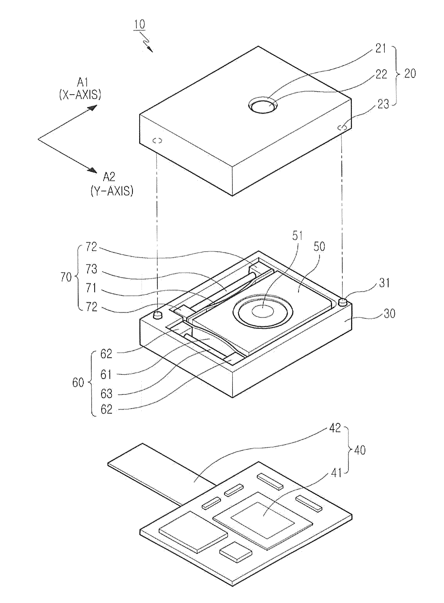
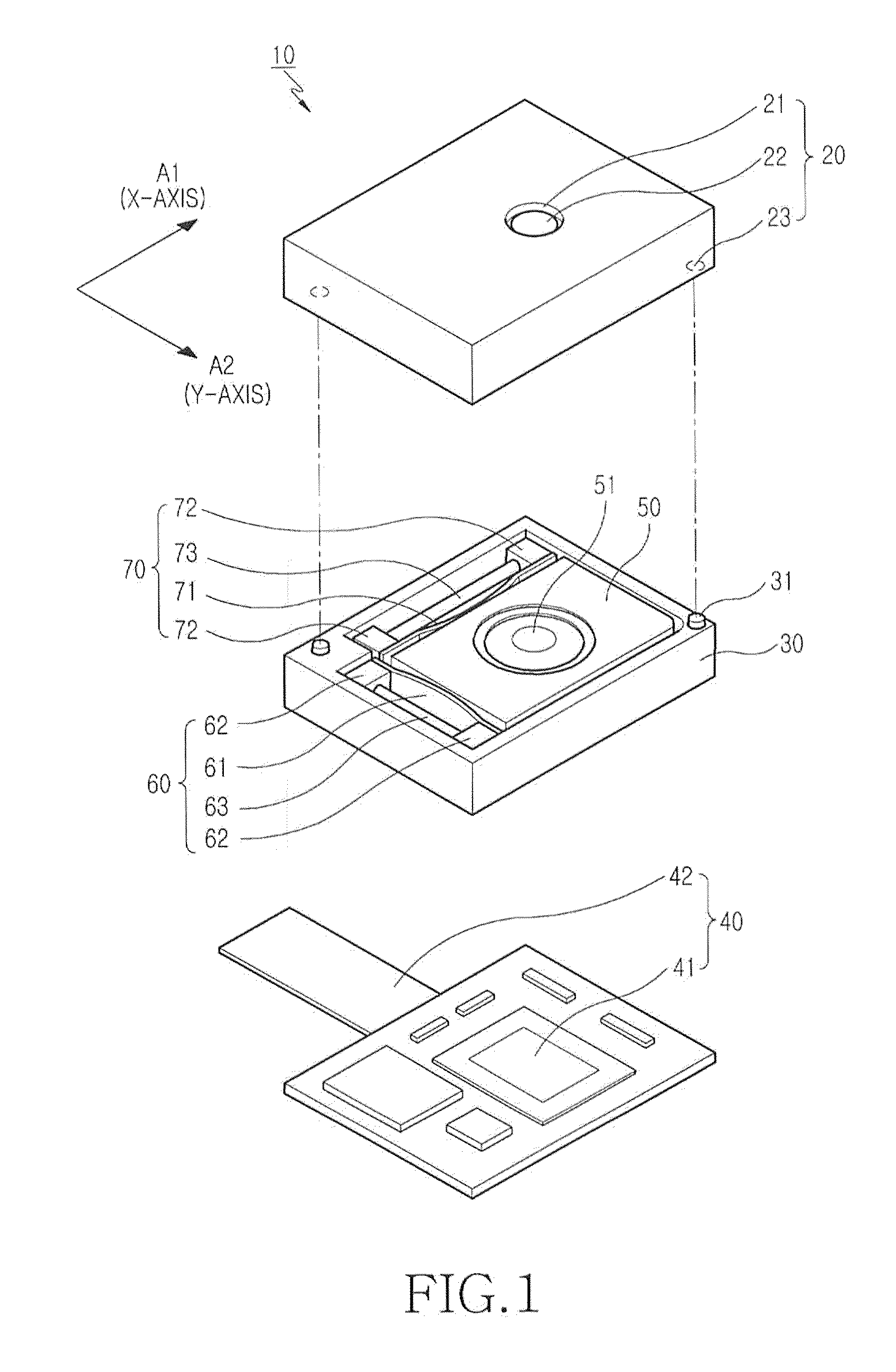
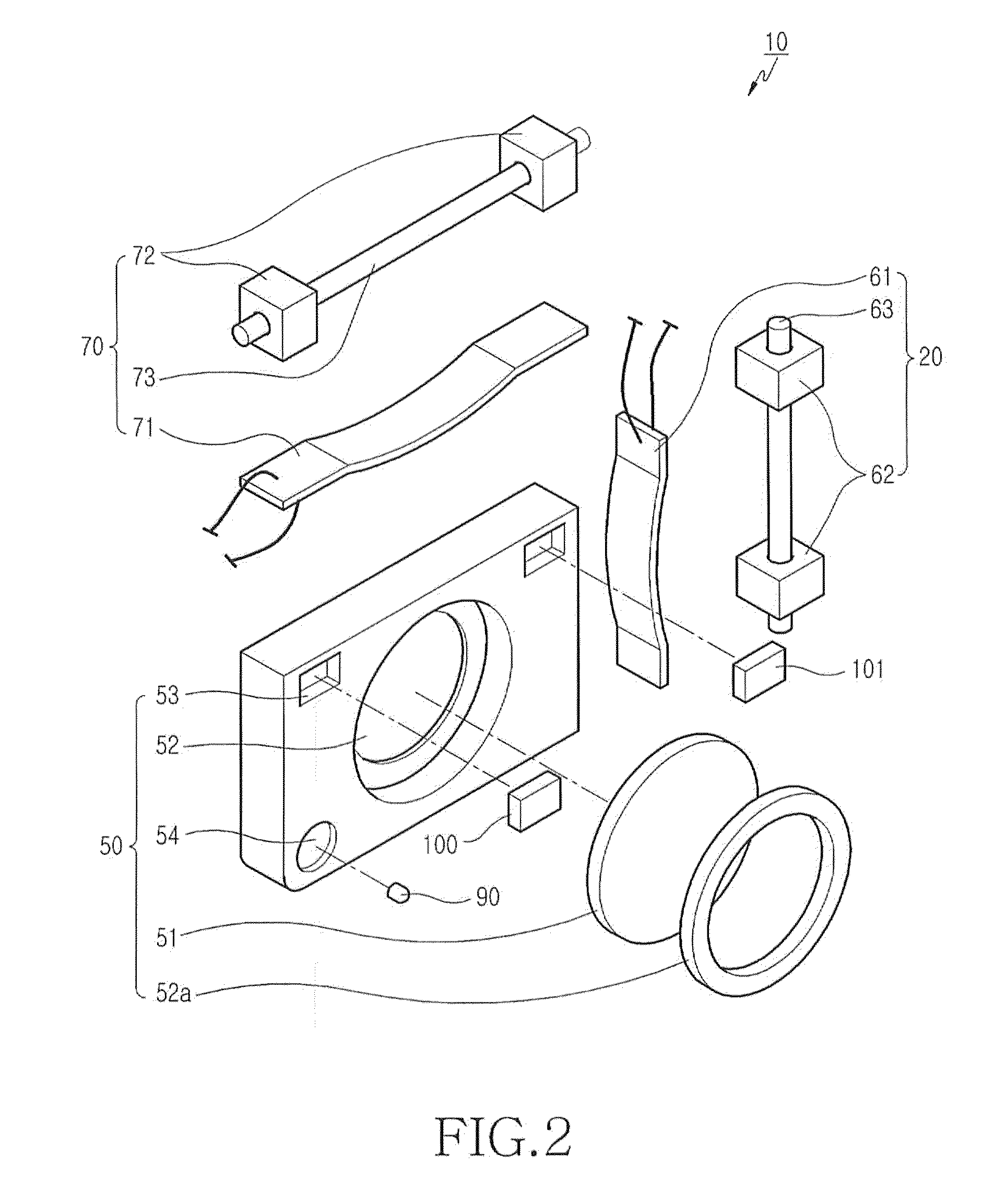
[0026]Referring to FIGS. 1 to 8, an optical image stabilizer 10 for a camera module in accordance with the present invention includes an upper housing 20 and a lower housing 30, a printed circuit board 40, a lens frame 50, a first driver 60 and a second driver 70, and a movement sensing controller 80. The upper housing 20 is joined together with the lower housing 30 preferably thr...


PUM


Abstract

Disclosed is an optical image stabilizer for a camera module using polymer elements which can be moved in a first direction and a second direction in the vicinity of the camera module. The optical image stabilizer includes an upper housing and a lower housing; a printed circuit board having an image sensor; a lens frame having a camera lens retained within the lower housing; first and second drivers disposed in the vicinity of the lens frame for moving the lens frame in first and second directions, respectively; and a movement sensing controller provided within the lower housing for sensing the amount of movement of the lens frame on the basis of the magnitude of a shaking of the camera module, so as to control the lens frame.

Description

PRIORITY[0001]This application claims priority under 35 U.S.C. §119(a) to an application entitled “Optical Image Stabilizer For Camera Module” filed in the Korean Industrial Property Office on Nov. 19, 2008 and assigned Serial No. 10-2008-0115263, the contents of which are hereby incorporated by reference.BACKGROUND OF THE INVENTION[0002]1. Field of the Invention[0003]The present invention relates to an optical image stabilizer for a camera module capable of moving in first and second directions around a camera module using polymer elements.[0004]2. Description of the Related Art[0005]In general, as a large amount of still cameras and digital video cameras are widely provided, consumers increasingly want to take pictures and videos in high quality. In particular, a Complementary Metal Oxide Semiconductor (CMOS) sensor is preferred over a Charge Coupled Device (CCD) sensor as an image sensor for digital cameras. The reason is that the CCD sensor has better characteristics in image qu...

Claims


Application Information

Patent Timeline
Patent Type & Authority Applications(United States)
IPC IPC(8): H04N5/228
CPCH04N5/23248H04N5/23287H04N5/23258H04N23/68H04N23/6812H04N23/687
Inventor SHIN, DOO-SIK
Owner SAMSUNG ELECTRONICS CO LTD
Why Eureka
Try Eureka