Adapter for attaching devices to endoscopes

a technology for attaching devices and endoscopes, which is applied in the field of adapters for attaching devices to endoscopes, can solve the problems of difficult use of endoscopes which have been repeatedly rested or repaired, the stiction properties of an instrument which may be used in a specific procedure are generally impossible to predict, and the complexity of instruments is high and expensive. achieve the effect of increasing stiction properties, increasing force, and increasing stiction properties

Active Publication Date: 2010-05-20
US ENDOSCOPY GROUP
View PDF51 Cites 85 Cited by
  • Summary
  • Abstract
  • Description
  • Claims
  • Application Information

AI Technical Summary

Benefits of technology

[0036]The centerline of the endoscopic instrument is purposefully misaligned with the virtual centerline of the invention, allowing a lens of the endoscope, or other optical detector, to be located closer to the outer diameter of the invention in order to facilitate an enhanced visual field of view when in a proper rotational alignment to other features. In a preferred embodiment, the distal stop and endoscope depth limiting features may be tapered along the center axial length to gradually decrease its diameter, distal to proximal, to create an offset for field of view enhancement.
[0053]The adapter may be used with an endoscope which is selected to be larger in diameter than the distal stop effective diameter and wherein a flange, when in contact with said endoscopic instrument prevents proximal to distal movement of the endoscope with respect to the flange. Alternatively, the endoscope is selected to be no larger in diameter than the distal stop, and the flange, once in contact with said endoscopic instrument and secured on said instrument by the securing means, prevents both proximal and distal movement of the endoscope with respect to the flange.

Problems solved by technology

Hence, the geometric size of an instrument which may be used in a specific procedure is generally impossible to predict.
The resulting instruments are complex and expensive, and so they are normally re-used, after cleaning and sterilization.
While it is feasible to design an externally-mounted device for a particular endoscope in its original condition, for example a 10 mm endoscope, it can be very difficult to use such a system on endoscopes which have repeatedly been resterilized or repaired.
As a result, it is hard to get an externally-mounted device to slide onto a used endoscope, and yet remain in a tightly locked state during the conduct of a medical procedure.
Elastic mountings that are tight enough for new endoscopes may not fit onto old endoscopes, while mountings that will fit can be too loose for stable positioning during procedures.
Even with an appropriate diameter, the externally-mounted device may rock or tilt when being inserted or removed, and there is a risk of detachment of the device from the endoscope while in the body.
While in principle a dedicated endoscopic instrument or a unique sized device can be provided for every endoscopic procedure and significant variant thereof, in practice this is a significant increase in expense in an already expensive field, and is not a preferred solution to the problem of fit and security.
Moreover, a coaxial “collet” type of system, as described by No. 7,204,804 Zirps et al., is not very adaptable, and requires a number of exchangeable parts to be tried before a particular endoscope can be used with a particular adapter.
This is not a desirable situation during surgery.
The coaxial “collet” systems represented by No. 7,204,804 Zirps et al., while an improvement in instrument grip over a pure elastic ring or similar embodiment, for example as represented by Pat. Nos. 5,320,630 and 5,462,559 to Ahmed, still are limiting in that the range of locking variability of the “collet” device is limited by the amount of radial compression the locking collar can attain on the collet “fingers” over a fixed axial length of travel.
The prior art embodiments are also further limiting in their effect on the visual field of view once mounted.
Such off axis lens placement, combined with a cap on the instrument projecting more distal to the instrument distal tip, creates a limiting effect called“tunnel vision”, due to looking through a tube where the walls constrict the field of view to a narrow central aperture.
The practice of operating the extending mechanism to create space that allows tissue to be drawn into a chamber for fastener attachment can lead to some confusion by the operator as instrument position of the distal tip (device length) along with field of view and focal distance of the optical system is changing device during actuation.
When space within the body cavity is limited such extension movement needed may not execute fully or may cause trauma or inadvertent loss of distal tip location.
As such, the requirement for movement of the instrument distal tip thus changing the working length when in the body cavity to generate a “tissue cavity” as a required by U.S. Pat. No. 7,189,247 Zirps et. al. is therefore a distinct disadvantage.
In practice this is not usually feasible, because with many closure devices described in the art, tissue needs to be drawn into a center zone of the deployment housing, to where the endoscope is located, to provide an effective closure.
Therefore, the endoscopic instrument must be positioned some distance proximal to the overall distal tip of the delivery device when actively engaging tissue for the purpose of effecting tissue manipulation or closure and therefore in that configuration or use the endoscope has a limited field of view.

Method used


Image

  • Adapter for attaching devices to endoscopes
  • Adapter for attaching devices to endoscopes
  • Adapter for attaching devices to endoscopes

Examples


Embodiment Construction

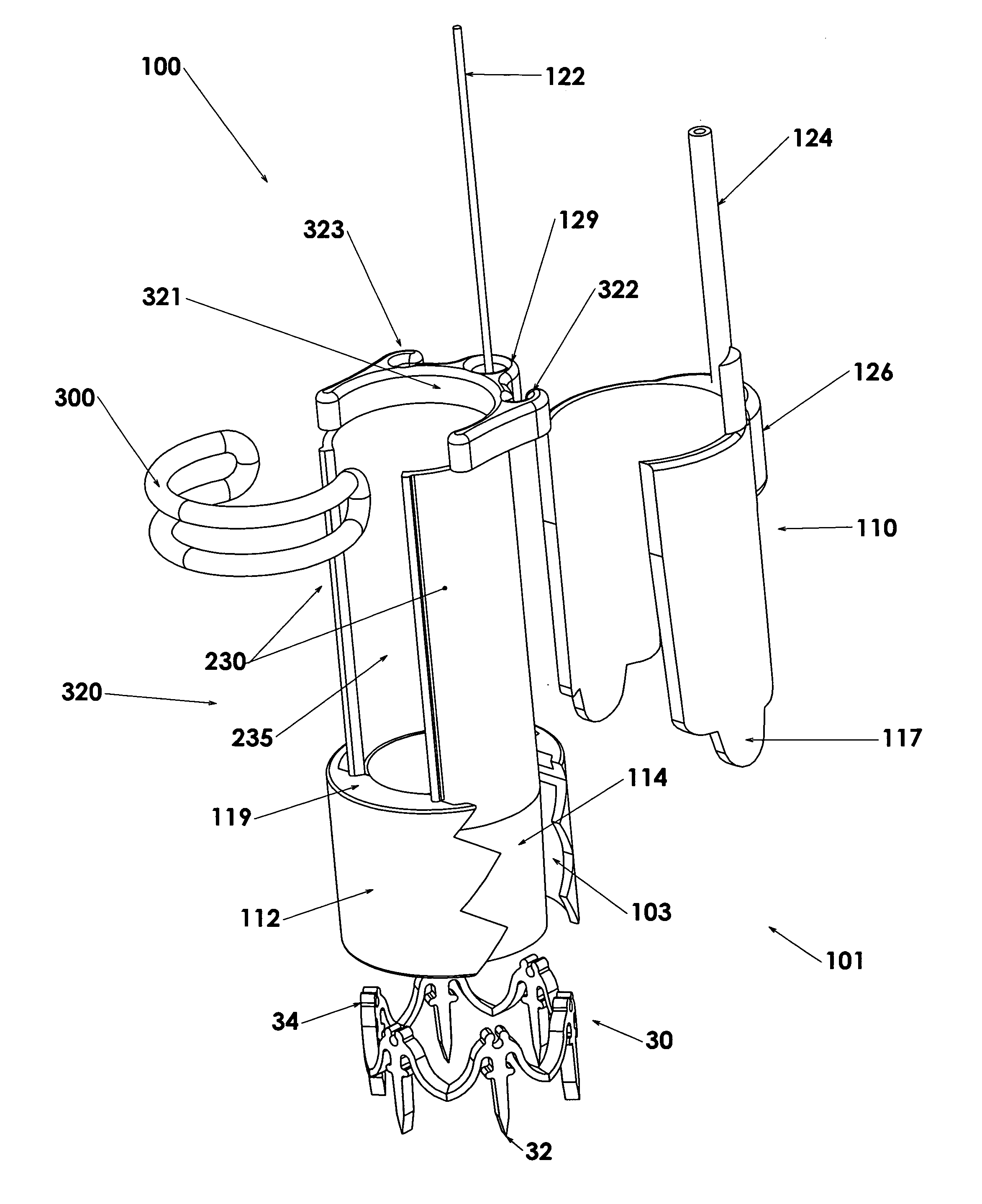
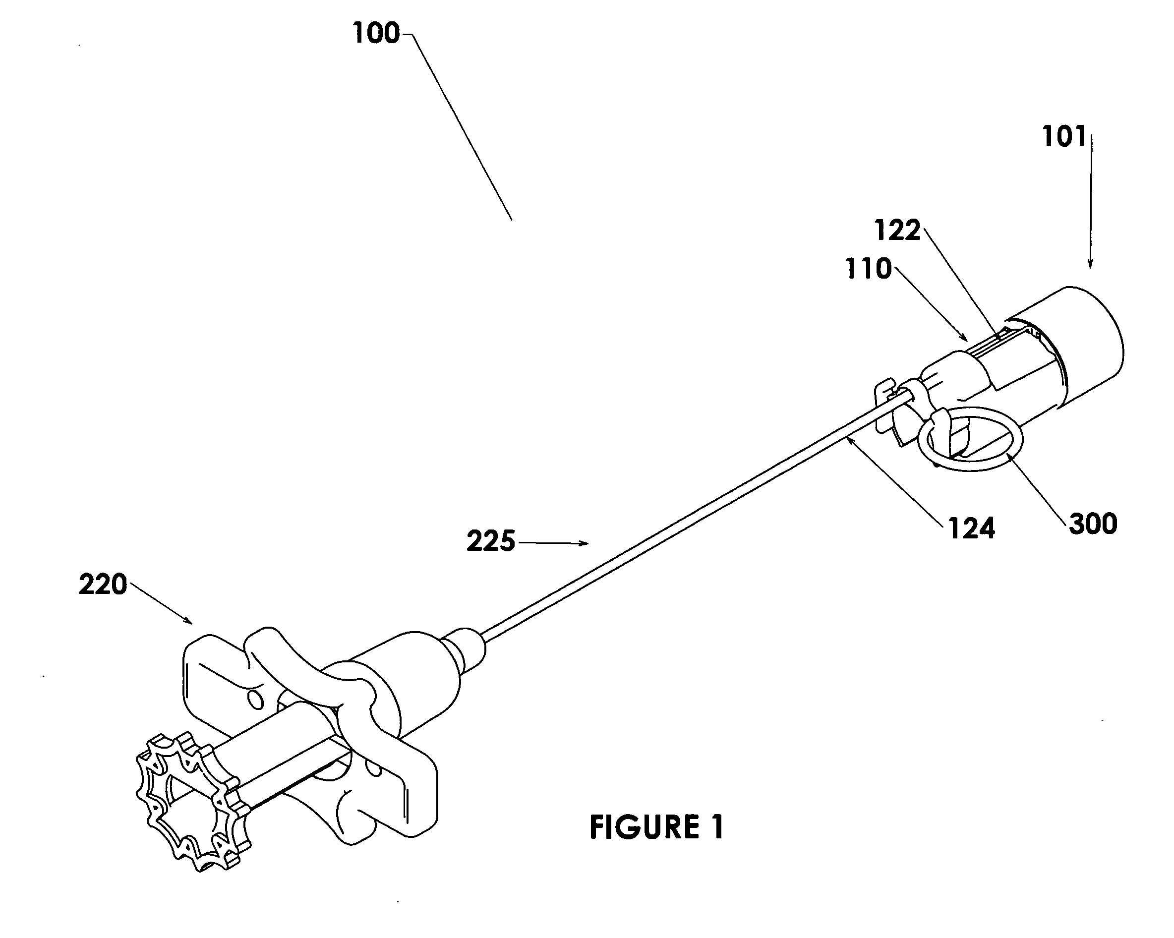
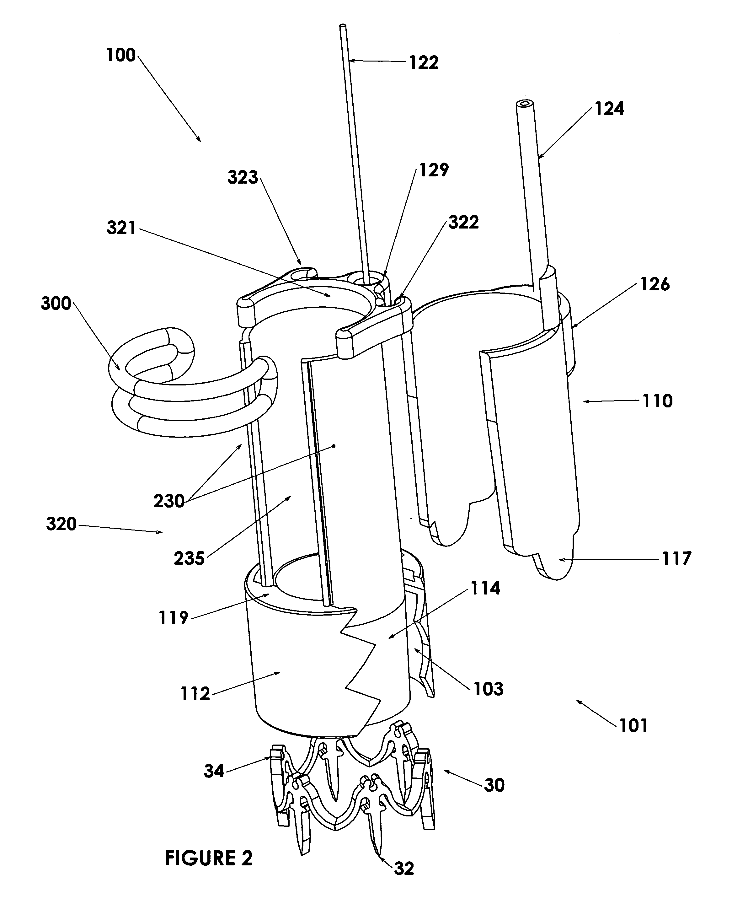
[0079]Particular embodiments of the invention are described in detail to enable the reader to understand the invention. In FIG. 1, an endoscopic instrument 100 is shown. This particular endoscopic instrument, generally described in priority document U.S. No. 61 / 199606, is designed to deliver a tissue clip to close an opening created during surgery, but the apparatus and method for affixing the clip delivery assembly to an endoscopic instrument are more general.

[0080]In FIG. 1, the device 100 has a handle assembly 220, with actuating means 225 connecting it to a deployment assembly 101. In this embodiment, the actuating means 225 comprise a wire sheath 124 and a wire 122. The wire sheath 124 is connected to pusher 110, which in this embodiment pushes a tissue-affixing clip out of assembly 101. The securing means 300 is in this instance an elastic band, shown in a non-securing position. The length of the actuating means 225 will be selected to be compatible with the length of the part...


PUM

PropertyMeasurementUnit
diameteraaaaaaaaaa
diameteraaaaaaaaaa
diameteraaaaaaaaaa

Abstract

An improved system for attaching devices to the distal end of endoscopic instruments is described. An attachment adapter comprises a distal stop, such as a complete or partial loop or cylinder, which limits the penetration of an endoscope into the adapter. The adapter has at least one flange protruding proximally along the endoscope. The adapter is secured on the endoscope by a securing means, which compresses the flange or flanges sufficiently to provide a friction fit. The flexibility of the inventive adapter system allows the adapter to work reliably with endoscopes that are used, damaged or repaired. The adapter may further provide a slit or window allowing viewing of the vessel wall by a lens on an endoscope, thereby improving the operator's ability to understand the location of the endoscope during operation. The adapter may carry any of a variety of devices, including devices for closing a surgical incision, or treating or manipulating tissue. Improvements are described in a number of areas to allow more flexible pairing of particular endoscopes or endoscopic instruments with devices to be carried on their exteriors, while maintaining a tightly locked position of the external device on the carrier.

Description

[0001]This application claims the benefit of the priority of U.S. provisional application No. 61 / 199606, filed Nov. 18, 2008, and No. 61 / 268813, filed Jun. 17, 2009. These applications are incorporated herein by reference in their entirety, where such incorporation is permitted.BACKGROUND[0002]Flexible endoscopes are axially elongate instruments that are navigable through natural body lumens of a patient for remotely evaluating and / or treating a variety of ailments. Endoscopes have viewing capability provided by fiber optic elements that transmit images along their length to the medical care provider. Endoscopes may be specifically configured in length, diameter, flexibility and lumen configuration to navigate to specific treatment areas in the body and conduct specific procedures. Such a specifically configured endoscope may be known by a specific or functional name, for example as a laparoscope, duodenoscope, colonoscope, sigmoidoscope, bronchoscope or urethroscope.[0003]In combin...

Claims


Application Information

Patent Timeline
Patent Type & Authority Applications(United States)
IPC IPC(8): A61B1/00A61B1/06A61B1/12B29C45/14
CPCA61B2017/0645A61B1/00089A61B17/068A61B1/00128A61B17/0644A61B1/00101A61B1/0014A61B2017/00668A61B1/00087A61B5/4839A61B1/00142A61B17/0057A61B2017/00473A61B2017/0641A61B2017/00296A61B17/00234A61B17/064
Inventor LABOMBARD, DENIS
Owner US ENDOSCOPY GROUP
Why Eureka
Try Eureka