Method and apparatus for addressing vascular stenotic lesions

Inactive Publication Date: 2010-05-20
FISHEL ROBERT S
View PDF3 Cites 80 Cited by
  • Summary
  • Abstract
  • Description
  • Claims
  • Application Information

AI Technical Summary

Problems solved by technology

Coronary and other vascular stenotic lesions can cause medical problems for people.
The extent of the disease can be severe and can result in heart attack (myocardial infarction) and stroke.
Such a method however is overly simplistic and does not account

Method used


Image

  • Method and apparatus for addressing vascular stenotic lesions
  • Method and apparatus for addressing vascular stenotic lesions

Examples


Embodiment Construction

[0011]While the present invention is susceptible of embodiment in various forms, there is shown in the drawings and will hereinafter be described presently preferred embodiments with the understanding that the present disclosure is to be considered an exemplification of the invention and is not intended to limit the invention to the specific embodiments illustrated.

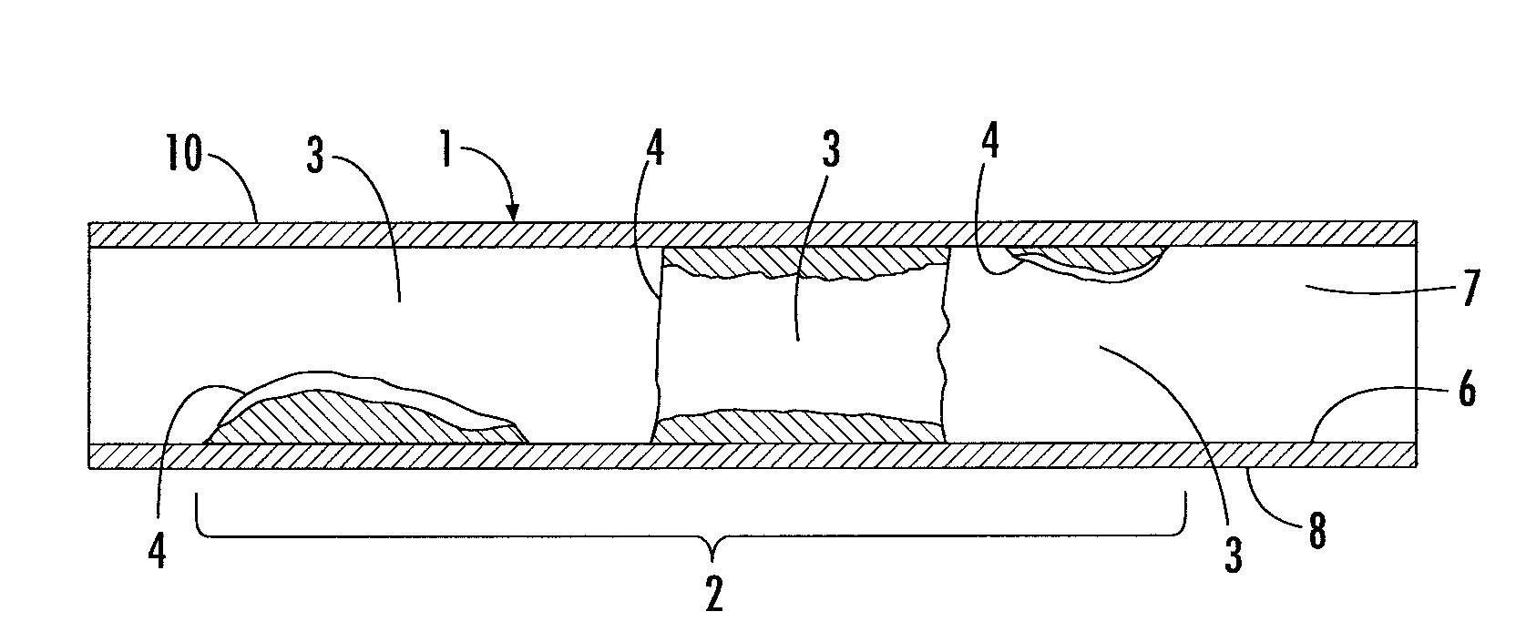
[0012]The reference numeral 1 designates generally a portion of a blood vessel have a stenosis zone 2 with a plurality of axially distributed occluded areas 3 of stenotic lesions 4. The lesions 5 extend inwardly from the epithelial wall 6 occluding the flow passage 7 between a proximal end portion 8 to a distal end portion 10. The blood flows in a direction from the proximal end 8 to the distal end 10.

[0013]The method includes addressing vascular stenotic lesions 3 in the vascular system of a patient like a human. The degree of stenosis is determined by measuring the size of the blood flow passage 7 at opposite ends of th...


PUM


Abstract

A method and apparatus are provided for addressing vascular stenotic lesions. The geometry of a stenotic lesion zone is determined and is used to determine pressure drop of blood flow across the lesion zone or a portion thereof. The pressure drop value is used to determine a treatment regimen for the stenotic lesion zone. The geometry if preferably a three dimensional geometry. The apparatus provides pressure drop values to a physician so the physician can treat the patient if treatment is needed and provides direction for treatment options as to type and degree.

Description

RELATED APPLICATIONS[0001]This application claims the benefit under 35 U.S.C. 119 (e) of U.S. Provisional Patent Application No. 61 / 115,769, filed Nov. 18, 2008, entitled, “Method For Modeling Of Hydrodynamic Pressure Drop Across A Series Of Coronary And Other Vascular Stenotic Lesion Sets Using Data Sets Acquired Via 3-Dimensional Intravascular Ultrasound”, and U.S. Provisional Patent Application No. 61 / 116,964, filed Nov. 21, 2008, entitled, “Method For Modeling Of Hydrodynamic Pressure Drop Across A Series Of Coronary And Other Vascular Stenotic Lesion Sets Using Data Sets Acquired Via 3-Dimensional Intravascular Ultrasound”, the entirety of which is incorporated herein by reference.FIELD OF INVENTION[0002]The present invention relates to a method of addressing occlusions in blood vessels to determine a treatment method or strategy. The significance of vascular stenosis is determined by the depth, the shape and the length of the stentic lesion and is correlated to predetermined p...

Claims


Application Information

Patent Timeline
IPC IPC(8): A61B8/04A61B5/00
CPCA61B5/026A61B5/02007
Inventor FISHEL, ROBERT S.
Owner FISHEL ROBERT S
Why Eureka
Try Eureka