Nostril dilator

a dilator and nose tube technology, applied in the field of devices, can solve the problems of lack of user modulation, lack of constant pressure of thorner and slater patents, limited amount of external devices, etc., to reduce the physical constriction of the airway, reduce the risk of snoring, and improve the nasal breathing efficiency

Inactive Publication Date: 2010-05-20
WIEN ABRAHAM
View PDF18 Cites 8 Cited by
  • Summary
  • Abstract
  • Description
  • Claims
  • Application Information

AI Technical Summary

Benefits of technology

[0018]The prosthesis can then be positioned inside an individual's nostrils by first deflection of the arch of the medial segment so as to temporarily, internally stress the prosthesis. This deflection of the arch of the media section produces the transient effect of causing each of the appendages to once again move toward one another, thus, facilitating the placement of each appendage within a nostril of an individual. Once positioned within each nostril of the individual, the deflection of the medial segment is released, and the internal stresses upon the prosthesis are uniformly distributed throughout the prosthesis. In this more relaxed / less stressed position, the forces / tension within this unitary structure of the prosthesis is equalized throughout the entire body of the prosthesis, including the lateral appendages. More specifically, the lateral appendages on each end of the prosthesis are sprung outward so as to apply a gentile, symmetric, uniformly force which vectors on the appendages so as to deflect the nostrils to a more open position. The internal tension on the medial section of the prosthesis also results in a deflection / tortional rotation of the medial section downward and at an angle that causes it to align flush with the skin right under the nose, so as to avoid any obstruction of the air passages into the nose.
[0019]Once the prosthesis is inserted into the user's nostrils, the recoil of the medial section, causes the appendage on each end thereof, applies a gentle and constant pressure on each of the nostrils, thereby opening the airway into nostrils and relieving the physical constriction of the airway. The internal nasal prosthesis of this invention, thus, can increase nasal breathing efficiency and thereby minimize snoring.

Problems solved by technology

When such restriction is encountered, for any one of number of reasons, breathing is shifted to the mouth, which in turn can result in snoring, and possibly other conditions associated therewith (e.g. restrictive apnea).
More specifically, the external devices, of the type illustrated by the Hand patent, are limited in the amount of expansive pressure that can be exerted upon each nostril by the adhesive forces that can be applied to the external surface of the nose.
Similarly, the internal devices of the type illustrated by the Thorner and Slater patents lack the ability to apply a constant pressure from with each nostril without periodic manual adjustment and the repositioning such device on a periodic basis.
Accordingly, while the external device prosthetic device of Hand is favored because of the constant pressure, spring tensioning element incorporated therein, it lacks the ability for user modulation; and, is otherwise dependent upon adhesives for its contact with the nasal passages.

Method used


Image

  • Nostril dilator
  • Nostril dilator
  • Nostril dilator

Examples


Embodiment Construction

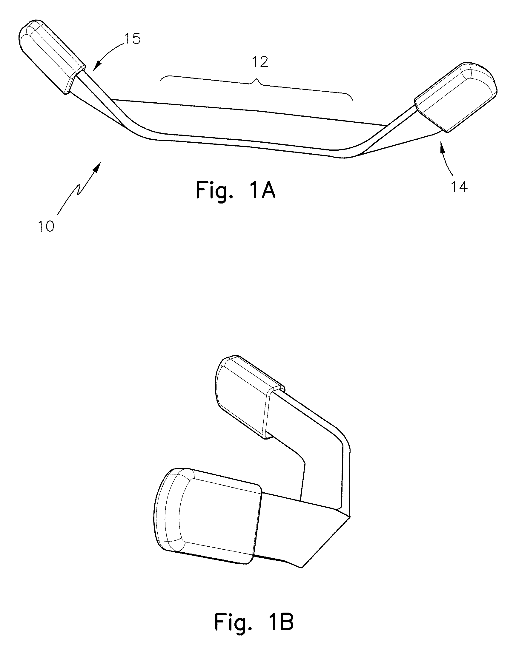
[0025]The reference numerals assigned to the various elements of the internal nasal prosthesis of this invention have the same numerical value where the elements in each Figure is the same or perform a function in common.

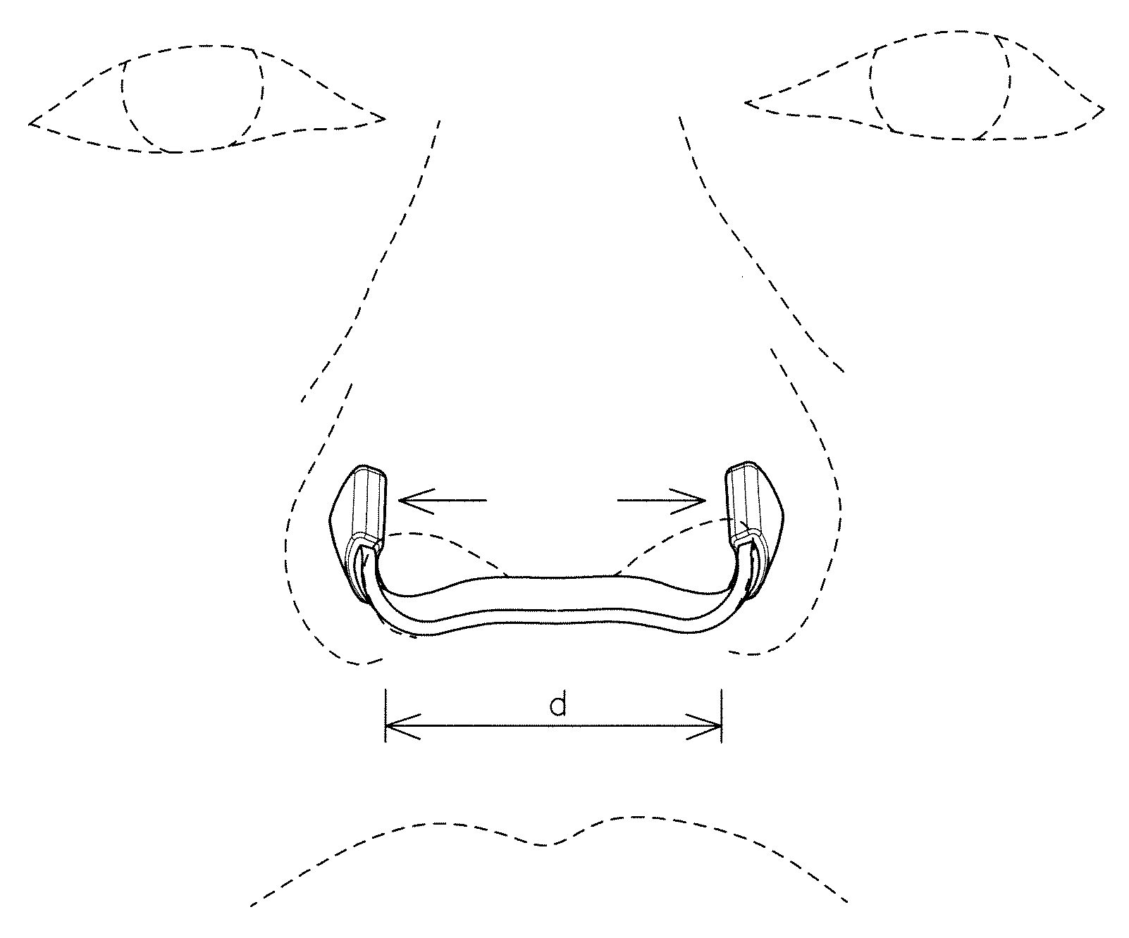
[0026]FIG. 1(a) depicts a preferred embodiment of the nasal prosthesis (10) of this invention having a medial segment (12) and two appendages (14, 15) on each end thereof. Each appendage (14, 15) is the formed so as to comprise the mirror image of the other. In the embodiment of the invention depicted in FIG. 1, the medial segment (12) is flat ribbon between each appendage (14, 15). As depicted in FIG. 1a, the appendages (14, 15) are inclined at an angle of at least about 30 degrees into the plane of the page, and at about 90 degrees from the horizontal. The relative orientation of each appendage to the medial segments is more fully appreciated when the prosthesis is view from the left end thereof (FIG. 1b) and from the right end thereof (FIG. 1c).

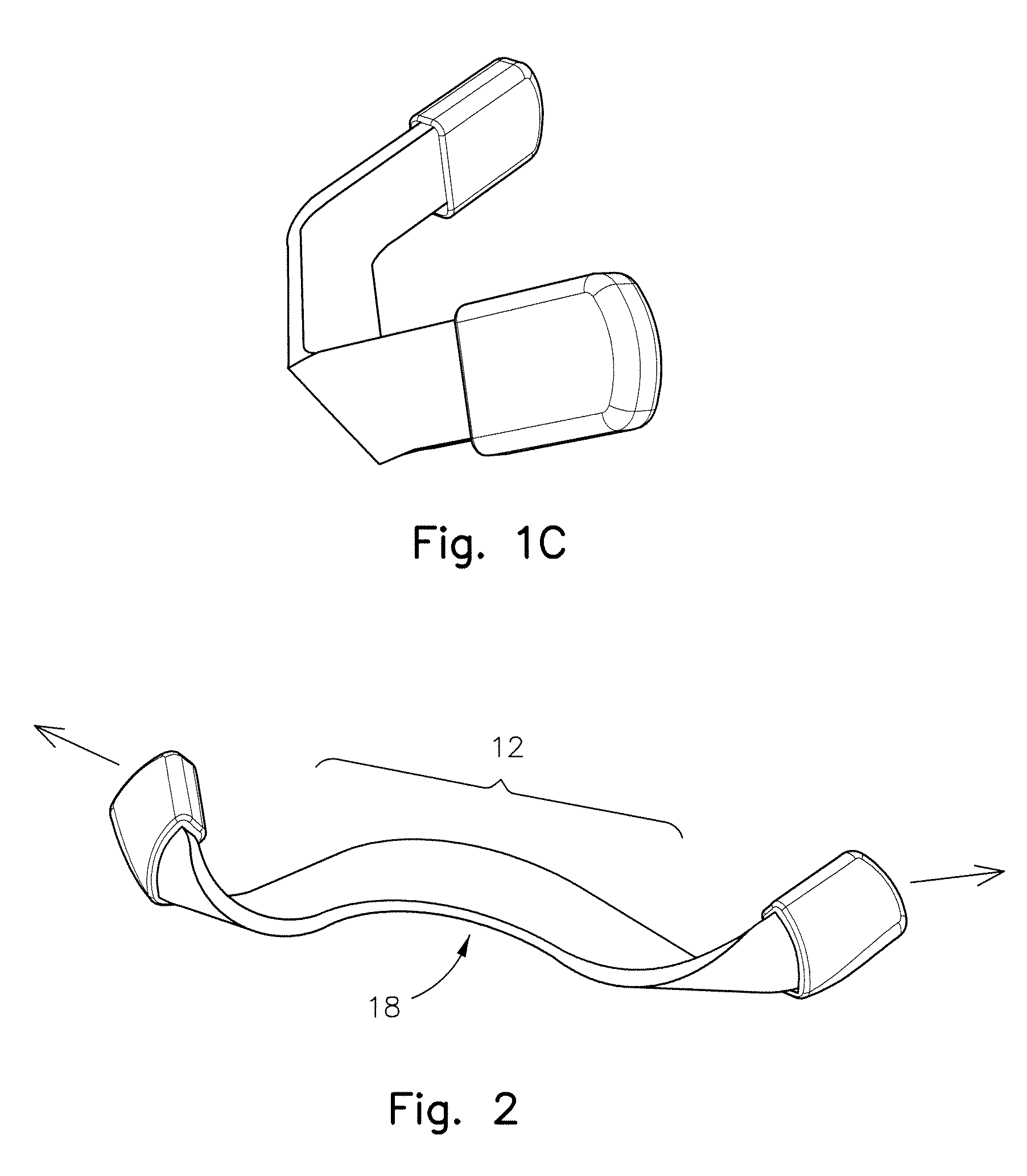
[0027]FIG. 2 depic...


PUM


Abstract

An internal nasal prosthesis of unitary construction. The prosthsis has three distinct segments, an arched medial segment and two lateral appendages on each end of the medial segment. Each appendage of this prosthesis is the mirror image of the other and is inclined at a compound angle, relative to said arched medial segment, so that each of said appendage is inclined, at an angle, into the plane of the page, of at least about 30 degrees, and at an angle, relative to the horizontal plane of the medial section, of about 90 degrees; and

Description

BACKGROUND OF THE INVENTION[0001]1. Field of the Invention[0002]This invention relates to a device. More specifically, this invention is directed to a device for relieving congestion and improve air flow in restricted nasal passages, by the dilation thereof with an internal prosthesis placed within the nasal passages of an individual. This prosthesis is adjustable, and under tension, so as to thereby exert constant pressure within each nasal passage to maintain such passages in a relatively dilated / open position.[0003]2. Description of the Prior Art[0004]The natural tendency is for human beings to breath through their nose, unless otherwise restricted from doing so. When such restriction is encountered, for any one of number of reasons, breathing is shifted to the mouth, which in turn can result in snoring, and possibly other conditions associated therewith (e.g. restrictive apnea).[0005]Over the years a number of devices have been developed to lessen the nasal restriction and impro...

Claims


Application Information

Patent Timeline
Patent Type & Authority Applications(United States)
IPC IPC(8): A61M29/02
CPCA61M29/00A61F5/08
Inventor WIEN, ABRAHAM
Owner WIEN ABRAHAM
Why Eureka
Try Eureka