
Installation for palleting combined with secure access

a technology of secure access and installation, applied in the field of installation, can solve the problems of robot installation, production loss, and the nature of the operator who needs to get close to the robot, and achieve the effect of high degree of safety

Inactive Publication Date: 2010-05-20
SIDEL PARTICIPATIONS SAS
View PDF9 Cites 55 Cited by
  • Summary
  • Abstract
  • Description
  • Claims
  • Application Information

AI Technical Summary

Benefits of technology

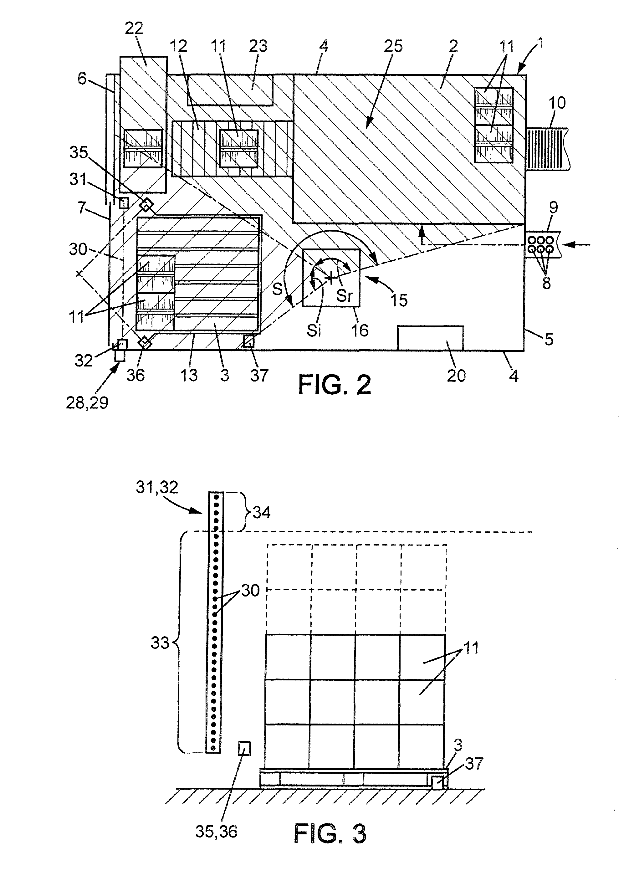
[0013]Still according to the invention, the steering control of the robot also manages all of the movements of said robot while still ensuring that it does not exit the work zone which is programmed, i.e. this steering control of the robot comprises means for defining work spaces wherein the robot is authorised to operate as well as means for causing its immediate and total stoppage if it leaves these authorised operating spaces.
[0014]According to another arrangement of the invention, the installation comprises a sensor which is associated to the access door to the pallet, said sensor authorising, by the intermediary of the steering control of the robot, the continuation of the activity of the robot in its restricted space if the operator has requested access to the palleting station, or causes the immediate and total stoppage of said installation in the event of the absence of an access request or in the case where said access door is manoeuvred before the receiving of the authorisation for opening which is given by the intermediary of a lighted indicator associated to the switch.

Problems solved by technology

Generally, robotic installations have, regardless of how they are, a nature of major dangerousness for the operators who need to get close to the robot.
These stoppages of the packaging machine cause production losses and they can also disturb the production upstream, such as is carried out, for example, during labelling or placing products into the immediate container.

Method used


Image

  • Installation for palleting combined with secure access
  • Installation for palleting combined with secure access
  • Installation for palleting combined with secure access

Examples


Embodiment Construction

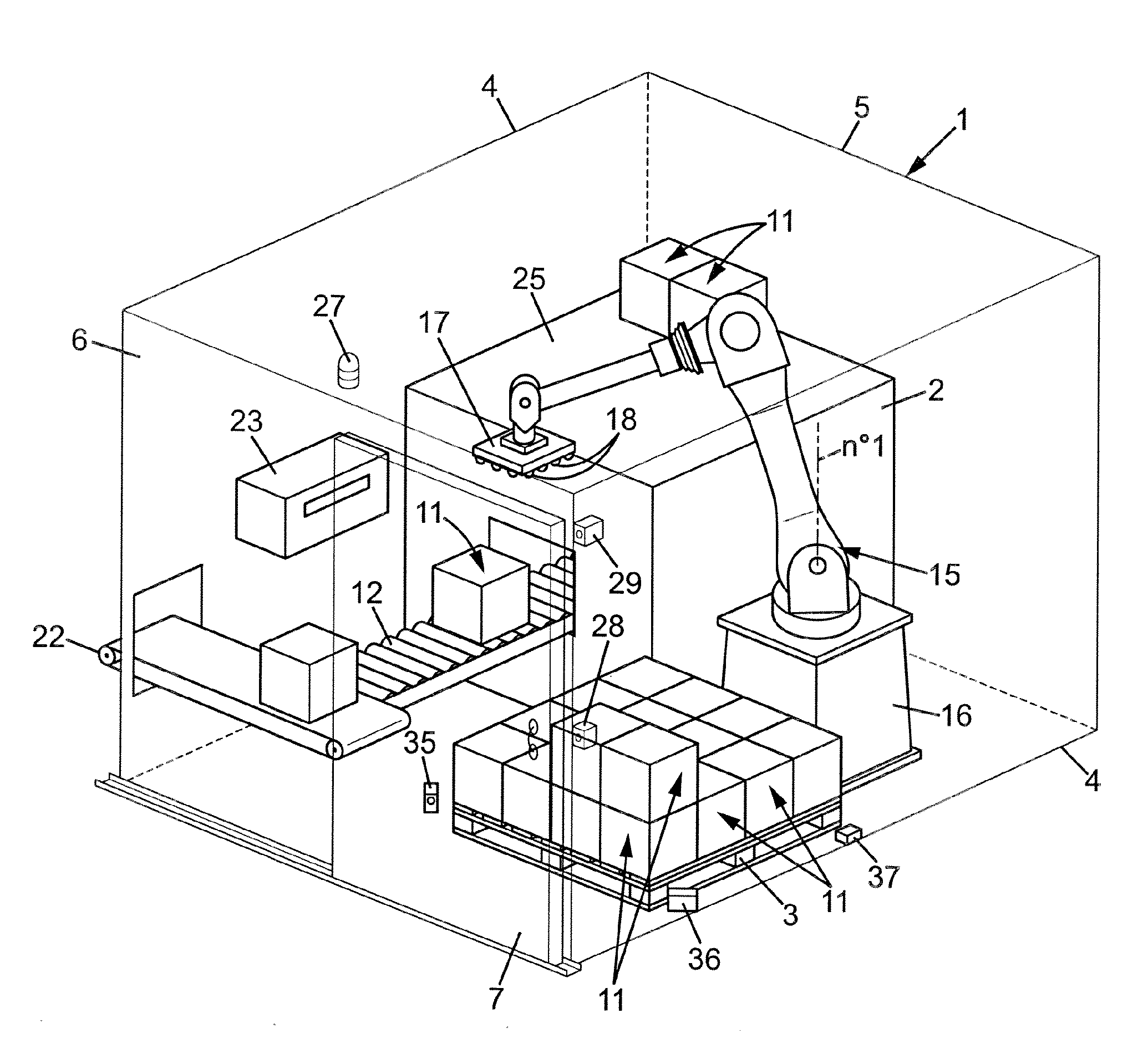
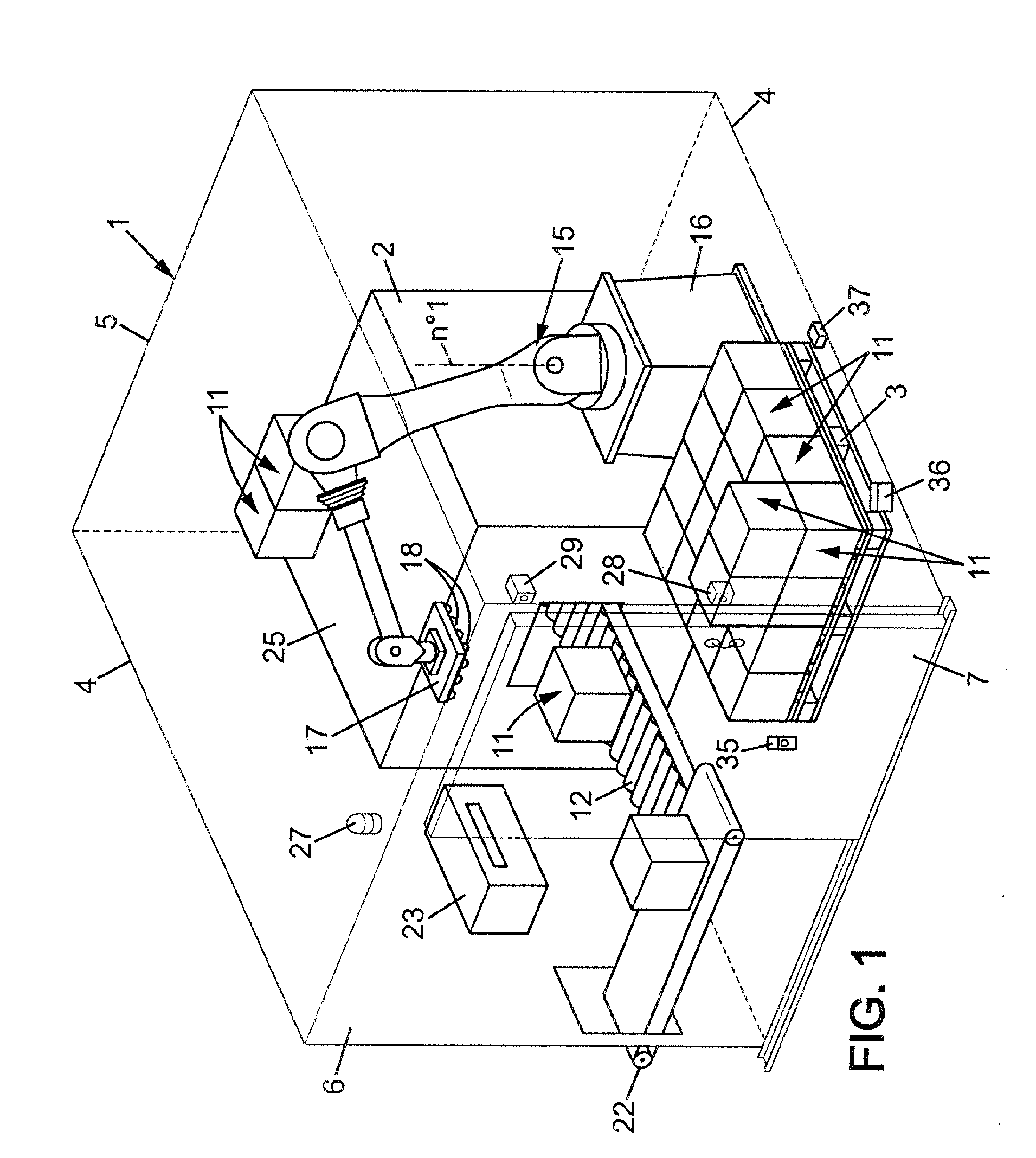
[0023]The installation shown in FIGS. 1 and 2, comprises, brought together in an enclosure 1 which is closed, a packaging machine 2 for products and a station for the pallet 3 where the automatic palleting operation takes place.

[0024]The enclosure 1 is closed by lateral walls 4, a rear wall 5 and a front wall 6 which comprises a door 7 in order to provide access to the pallet 3 which is located at the palleting station.

[0025]The machine 2 for conditioning is, for example, a machine of the type of that described in FR 2 907 100. It is fed with products 8 regularly by means of a conveyor 9, shown in FIG. 2, which introduces said products 8 by the rear wall 5 of the enclosure 1. This machine 2 further comprises a bin 10, also shown in FIG. 2, which makes it possible to supply it with carton blanks for the converting operation of the cases 11.

[0026]The products 8 are positioned in the cases 11 by the machine 2 and these cases 11 exit from said machine 2 onto a conveyor 12 which extends ...


PUM


Abstract

The installation is constituted of a machine (2) for packaging products (8) and of a robotic palleting station arranged in the same enclosure (1) provided with a door (7) that offers access to said palleting station.This installation comprises means which limit the range of movement of said robot (15) in said closed enclosure (1) in order to concentrate the displacements of its gripping head (17) in a restricted space which does not overlap onto the safety space which is defined according to a minimum distance measured from the immaterial barrier located in the enclosure 1, in the vicinity of the door (7).These means for limiting the range of movement of the robot (15) are comprised of a cam of the electric type, said cam limits, under the control of the steering control of said robot, the amplitude of the movement of said robot (15) around its main axis no. 1 and it can also reduce its speed of movement.

Description

FIELD OF THE INVENTION[0001]This invention relates to an installation which comprises, in a combined manner, a robotic station for palleting carton cases and a packaging machine which converts said cases and carries out their filling with products that have been conditioned beforehand.DESCRIPTION OF THE PRIOR ART[0002]Generally, robotic installations have, regardless of how they are, a nature of major dangerousness for the operators who need to get close to the robot.[0003]As such, for this type of robotic palleting installation, the operations of removing full pallets and inserting empty pallets are generally carried out by using a conveyor of the automatic type; however, such an installation implies the use of a surface on the ground that is much greater.[0004]For compact installations, such as that which is the object of the invention, wherein the robotic palletizer is combined directly with a machine that carries out the packaging of products, it is conventional to secure the in...

Claims


Application Information

Patent Timeline
Patent Type & Authority Applications(United States)
IPC IPC(8): G06F7/00B65G1/00B25J9/18
CPCB25J9/1676F16P3/14B65G2207/40B65G61/00F16P3/08F16P3/144
Inventor MOUGIN, DIDIERALIX, CHRISTOPHE
Owner SIDEL PARTICIPATIONS SAS
Learn More