
Reconfigurable portable powered tool and method of reconfiguring such a tool

a portable, powered tool technology, applied in the field of portable power tools, can solve problems such as prone to being damaged, user may be required to improvise, and potentially awkwardly supporting the tool, and achieve the effects of avoiding damage, being convenient to carry, and being convenient to carry

Inactive Publication Date: 2010-05-27
ECHO INCORP
View PDF12 Cites 16 Cited by
  • Summary
  • Abstract
  • Description
  • Claims
  • Application Information

AI Technical Summary

Problems solved by technology

Aside from the fact that the working component adds length, it also is prone to being damaged since it remains fully exposed with the unit in a storage / transportation configuration.
This is particularly a problem in the landscaping environment wherein the tool may be placed in an unprotected state in a truck or upon a trailer where it may be intermixed with other equipment or materials.
Another problem with this type of tool is that it is normally configured to be operated primarily in a single orientation.
Often, field conditions will require that a user reorient the working component, potentially into positions that were not contemplated by its design.
Thus, a user may be required to improvise and potentially awkwardly support the tool during all or part of a particular operation.
Extended use of a tool in an unintended orientation may cause user fatigue, and in a worst case an injury.
However, this generally is difficult and time consuming enough that it will not be carried out by a user on a work site.
Additionally, this operation generally requires specific tools which may not be kept on hand.

Method used


Image

  • Reconfigurable portable powered tool and method of reconfiguring such a tool
  • Reconfigurable portable powered tool and method of reconfiguring such a tool
  • Reconfigurable portable powered tool and method of reconfiguring such a tool

Examples


Embodiment Construction

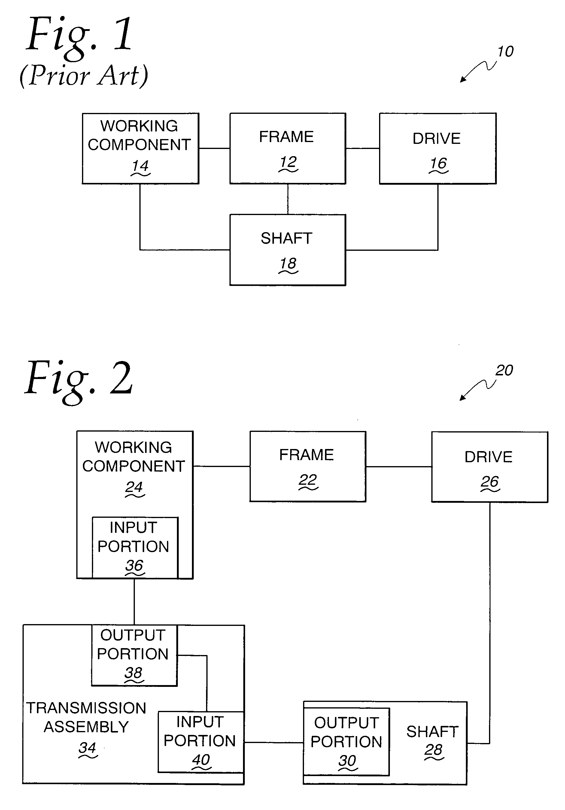
[0049]In FIG. 1, a schematic representation of a conventional, portable powered tool, into which the present invention can be incorporated, as shown at 10. The tool 10 consists of a frame 12 upon which a working component 14 is provided for performing an operation. A drive 16 is provided on the frame 12 for operating the working component 14 through a shaft 18. An exemplary form of the tool 10 is shown in U.S. Pat. No. 5,013,282. With this configuration, the working component 14 has a fixed relationship to the frame 12. Consequently, the design is such that it is contemplated the user will support and operate the tool in a predetermined orientation. At the same time, the fixed configuration for the tool does not permit it to be compacted appreciably for transportation and storage.

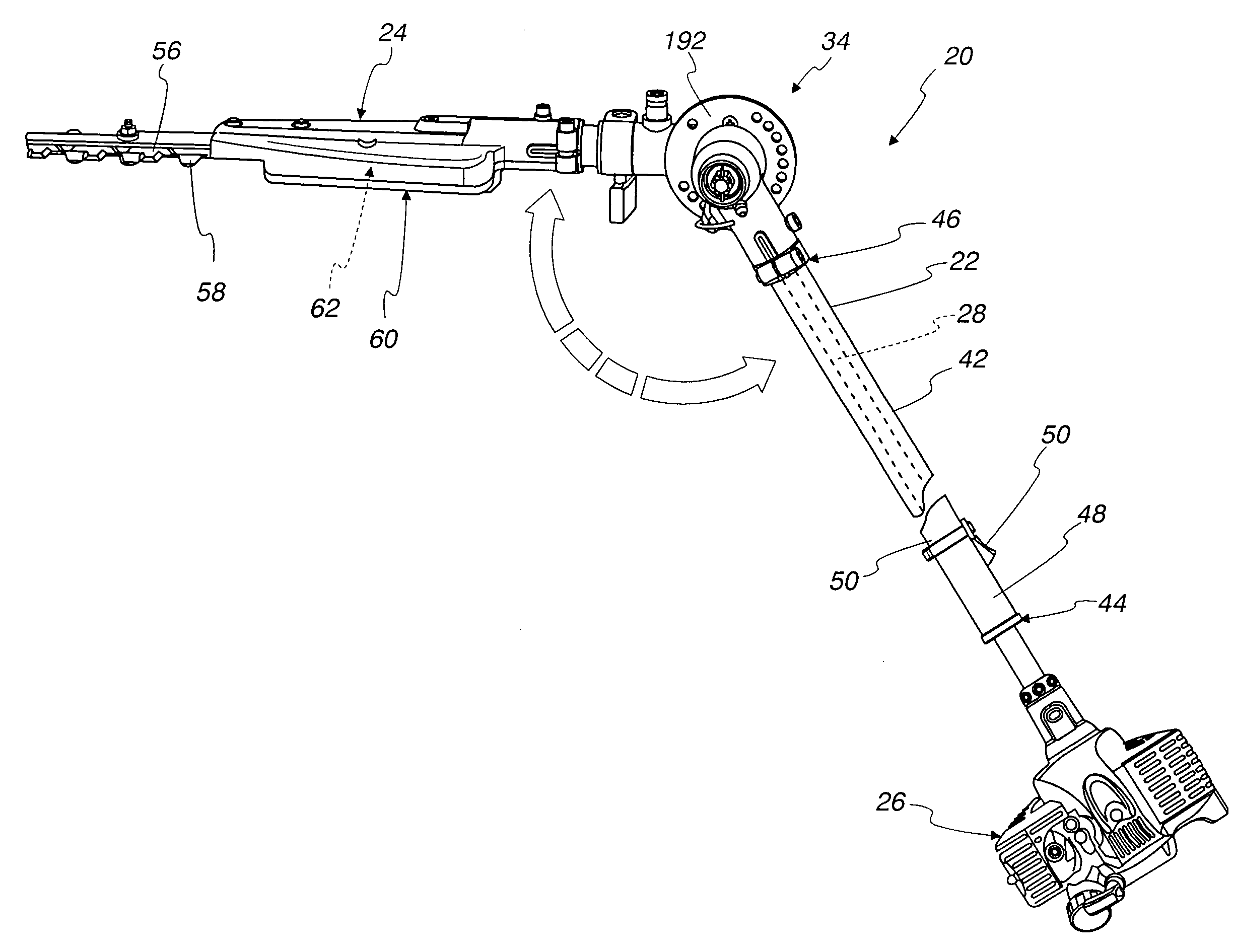
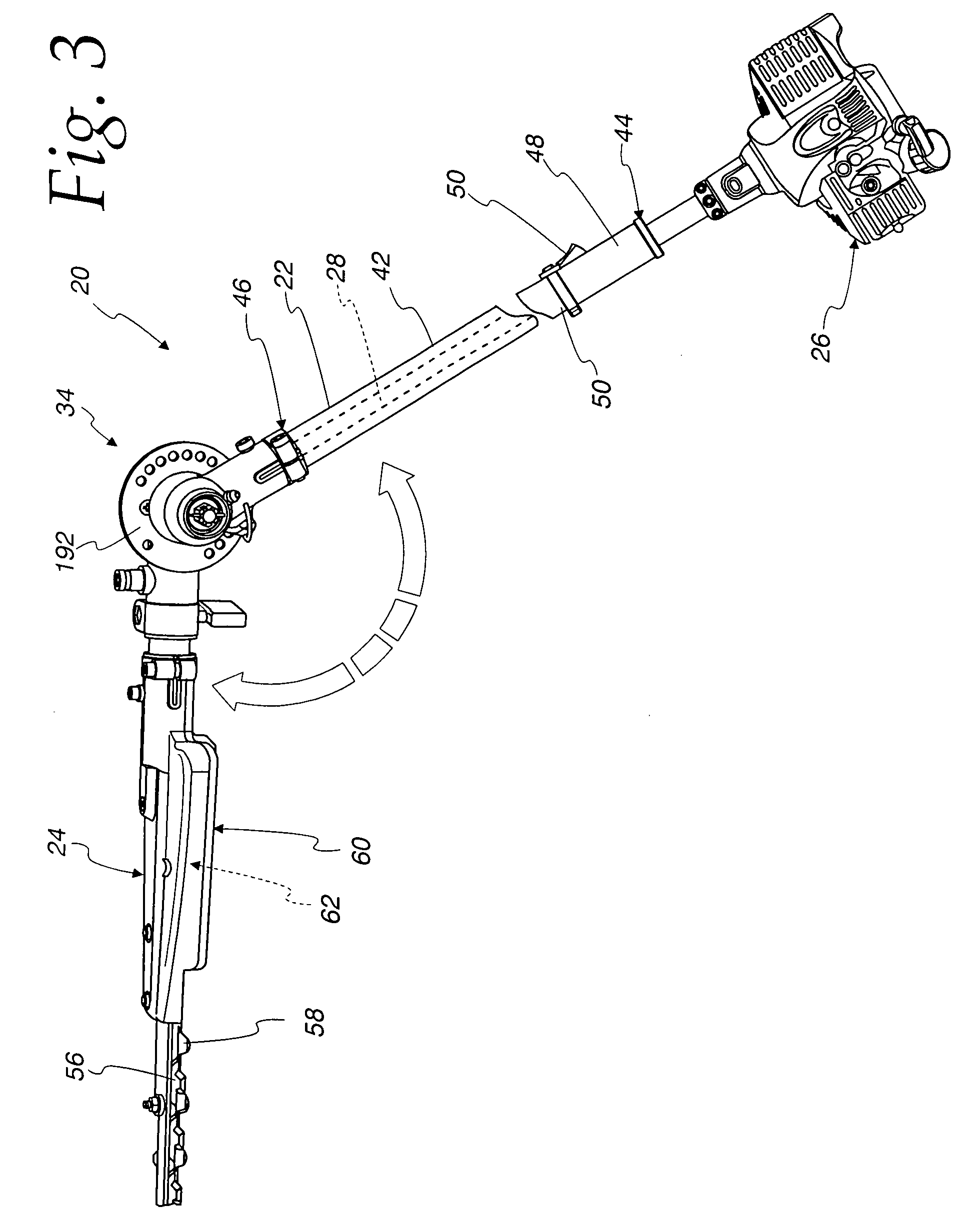
[0050]A schematic representation of a portable powered tool, according to the present invention, is shown in FIG. 2 at 20. The tool 20 has an arrangement of components that is similar to that for the tool 1...


PUM

PropertyMeasurementUnit
drive forceaaaaaaaaaa
transmissionaaaaaaaaaa
lengthaaaaaaaaaa

Abstract

A portable powered tool has a frame, a working component on the frame for performing an operation, a drive on the frame for operating the working component, a shaft having a first output portion that is driven by the drive around a first axis to thereby cause operation of the working component, and a transmission assembly operatively connected to the first output portion of the shaft to transmit a drive force from the first output portion to the working component to thereby cause operation of the working component.

Description

BACKGROUND OF THE INVENTION[0001]1. Field of the Invention[0002]This invention relates to portable, powered tools and, more particularly, to tools having a working component driven by a shaft.[0003]2. Background Art[0004]Portable, powered tools are used in many different industries and for many different applications by both professionals and non-professionals. Many different types of such tools are utilized in the landscaping industry. In this industry, the working component may be: a rotary, flexible line trimmer; a cutter utilizing an endless moving chain; a cutter with relatively movable blades, etc.[0005]In the landscaping industry, these types of tools are commonly made with elongate housings which permit an extended reach and controlled placement of the working component at an operating site. For example, working components that utilize reciprocating cutting blades to trim hedges, and the like, are often made with elongate housings to allow cutting at relatively high elevatio...

Claims


Application Information

Patent Timeline
Patent Type & Authority Applications(United States)
IPC IPC(8): A01G3/00A01D34/00
CPCA01D34/90Y10T29/49716A01G3/00F16H1/006
Inventor PETERSON, BRENT
Owner ECHO INCORP
Learn More