Helicopter

a helicopter and propeller technology, applied in the field of helicopters, can solve the problems of increasing the noise in the cabin, the arrangement position of the propeller and the airframe, and the width of the helicopter is larger than the one in the cabin, so as to prevent the increase in the size of the airframe and achieve high-speed flight

Inactive Publication Date: 2010-05-27
MITSUBISHI HEAVY IND LTD
View PDF3 Cites 36 Cited by
  • Summary
  • Abstract
  • Description
  • Claims
  • Application Information

AI Technical Summary

Benefits of technology

[0033]With this configuration, the one propeller can be moved to the right side of the airframe and another propeller can be moved to the left side of the airframe. This creates forward thrust on both the left and right sides of the airframe. Thus, forward thrust can be effectively created without producing a moment about the center of gravity acting on the helicopter.
[0034]According to the helicopter of the present invention, it is possible to cause the propeller to create thrust that cancels out the torque generated by the rotation of the main rotor when the propeller is located behind the airframe by the propeller supporting portion and to cause the propeller to create forward thrust when the propeller is located at the side of the airframe. This leads to advantages in that an increase in size of the airframe is prevented and high-speed flight can be achieved.

Problems solved by technology

However, the technique disclosed in Patent Document 1 and the technique in which the propeller is disposed on a side of the airframe have a problem in that the arrangement positions of the propeller and the airframe are close compared to the conventional arrangement position of the propeller.
More specifically, because the airframe has a cabin, such as a cockpit, in which passengers sit, a close arrangement of the propeller and the cabin causes the problem that the noise produced by the propeller increases the noise in the cabin.
On the other hand, the technique disclosed in Patent Document 2 and the technique in which the propeller is disposed on a side of the airframe have a problem in that the width of the helicopter is larger than that of the conventional helicopter because of the presence of the blade extending sideways on the airframe and the propeller disposed on a side of the airframe.
Such an increase in width of the helicopter increases the space necessary for taking off and landing, as well as the space necessary for parking the helicopter, leading to a problem in that the operational restrictions are tightened.

Method used


Image

  • Helicopter
  • Helicopter
  • Helicopter

Examples


first embodiment

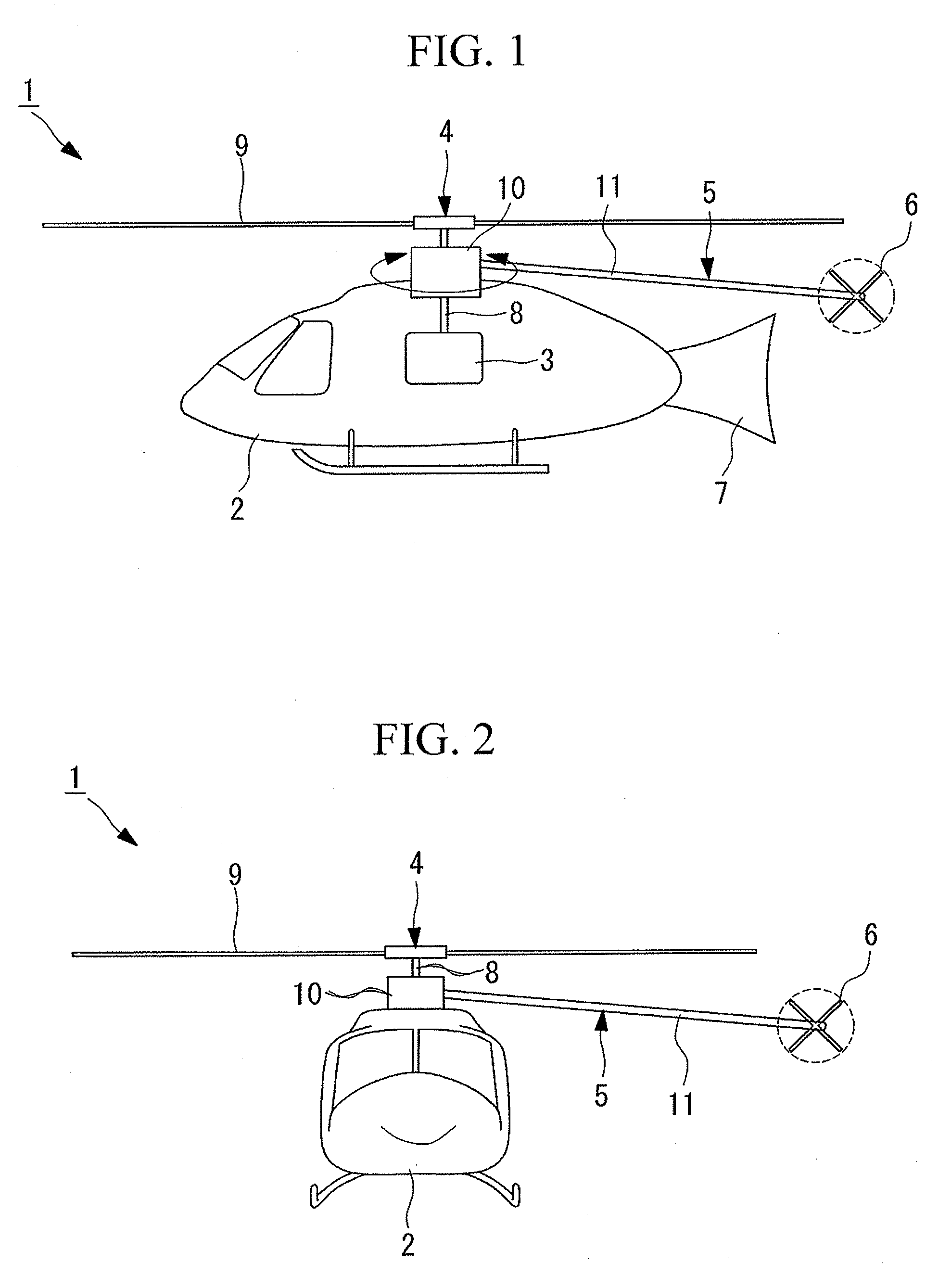
[0054]Referring to FIGS. 1 to 3, a helicopter according to a first embodiment of the present invention will be described below.

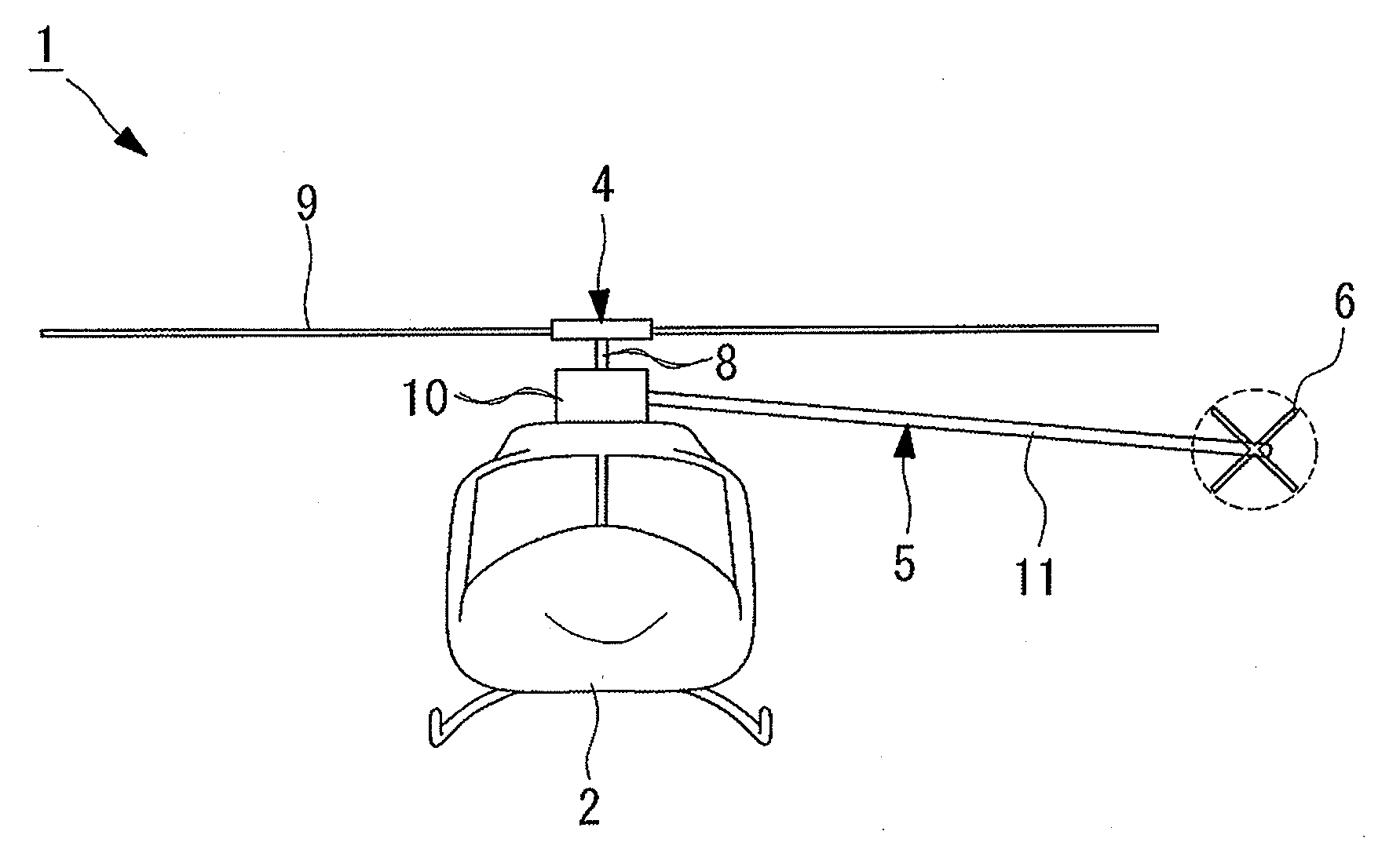
[0055]FIG. 1 is a side view for explaining the configuration of a helicopter according to this embodiment. FIG. 2 is a front view for explaining the configuration of the helicopter in FIG. 1, during high-speed flight.

[0056]A helicopter 1 of this embodiment is a helicopter that prevents an increase in size of an airframe and an increase in cabin noise, and also achieves high-speed flight.

[0057]As shown in FIGS. 1 and 2, the helicopter 1 includes an airframe 2 having a cabin or the like in which passengers sit, a main rotor 4 that is rotationally driven by an engine 3 disposed in the airframe 2, and a propeller 6 supported by a propeller supporting portion 5 so as to be rotatable.

[0058]As mentioned above, the airframe 2 has the cabin and the engine 3, and a vertical tail (tail) 7 extending substantially in the vertical direction (top-bottom direction in FIG. 1...

second embodiment

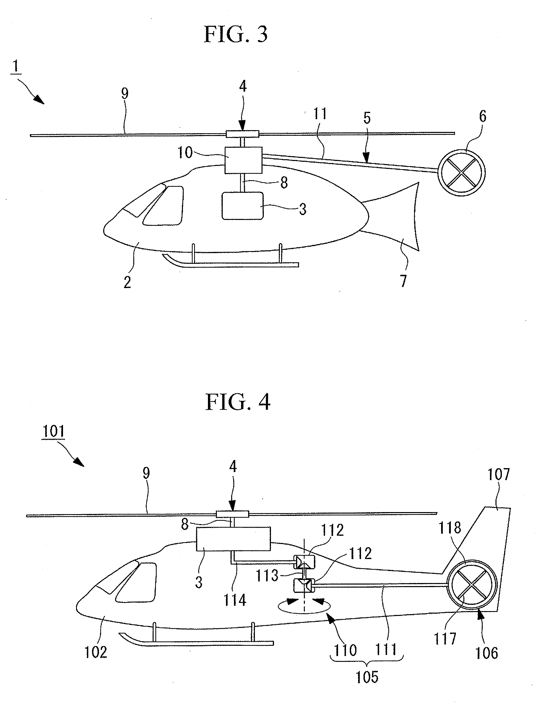
[0096]Now, referring to FIGS. 4 to 6, a second embodiment of the present invention will be described.

[0097]Although a helicopter according to this embodiment has the same basic configuration as that according to the first embodiment, it differs from that according to the first embodiment in the configuration of the propeller supporting portion. Therefore, in this embodiment, only the configuration in the vicinity of the propeller supporting portion will be described using FIGS. 4 to 6, and explanations of the other structures will be omitted.

[0098]FIG. 4 is a side view for explaining the configuration of the helicopter according to this embodiment. FIG. 5 is a front view for explaining the configuration of the helicopter in FIG. 4, during high-speed flight.

[0099]The components that are the same as those according to the first embodiment will be denoted by the same reference numerals, and explanations thereof will be omitted.

[0100]As shown in FIGS. 4 and 5, a helicopter 101 according...

third embodiment

[0134]Now, referring to FIG. 7, a third embodiment of the present invention will be described.

[0135]Although a helicopter according to this embodiment has the same basic configuration as that according to the first embodiment, it differs from that according to the first embodiment in the configuration of the propeller supporting portion. Therefore, in this embodiment, only the configuration in the vicinity of the propeller supporting portion will be described using FIG. 7, and explanations of the other structures will be omitted.

[0136]FIG. 7 is a front view for explaining the configuration of the helicopter according to this embodiment.

[0137]The components that are the same as those according to the first embodiment will be denoted by the same reference numerals, and explanations thereof will be omitted.

[0138]As shown in FIG. 7, a helicopter 201 according to this embodiment includes an airframe 2 having a cabin or the like in which passengers sit, a main rotor 4 that is rotationally...


PUM


Abstract

A helicopter capable of preventing an increase in size of an airframe and achieving high-speed flight is provided. Provided is an airframe for supporting a main rotor so as to be rotatable, a propeller having a plane of rotation intersecting a plane of rotation of the main rotor, a propeller supporting portion that supports the propeller so as to be movable between positions behind and at the side of the airframe, and a tail disposed on the airframe, having a surface intersecting the plane of rotation of the main rotor.

Description

TECHNICAL FIELD[0001]The present invention relates to helicopters.BACKGROUND ART[0002]In general, forward thrust of a helicopter is obtained by tilting the direction of thrust produced by the main rotor in the forward direction. Helicopters having such a configuration have a maximum speed of from about 260 km / h to about 280 km / h (from about 140 kt to about 150 kt).[0003]This maximum speed is determined by the aerodynamic limit of the mechanism that produces thrust with the main rotor. Even helicopters that have challenged the maximum speed record had a maximum speed of about 370 km / h (about 200 kt).[0004]If the speed of helicopters can be increased, the traveling time is reduced. This leads to an advantage in that, for example, by switching the transportation to isolated islands from conventional airplanes to helicopters, transportation that can provide more flexible operation than the use of airplanes can be obtained. Furthermore, there is another advantage in that rescue operation...

Claims


Application Information

Patent Timeline
Patent Type & Authority Applications(United States)
IPC IPC(8): B64C27/82
CPCB64C27/04B64C27/12B64C2027/8254B64C2027/8236B64C27/82
Inventor NAKAYAMA, SHUICHITSUKADA, HARUMI
Owner MITSUBISHI HEAVY IND LTD
Why Eureka
Try Eureka