
In-vehicle device, remote control system, and remote control method

a portable terminal and in-vehicle technology, applied in the direction of mechanical pattern conversion, instruments, navigation instruments, etc., can solve the problems of high device cost, high price, and the inability to effectively use the display of the in-vehicle devi

Inactive Publication Date: 2010-05-27
FUJITSU GENERAL LTD
View PDF11 Cites 43 Cited by
  • Summary
  • Abstract
  • Description
  • Claims
  • Application Information

AI Technical Summary

Problems solved by technology

However, multifunctional in-vehicle devices incur a high cost of the devices, and high price is not preferable for users.
Therefore, the display of the in-vehicle device cannot be effectively used.
Therefore, even when the in-vehicle device having a larger display area than that of the portable terminal device is used, the display size of the display screen of a navi-application displayed on the in-vehicle device is not sufficiently large, and has a problem in visibility.
Therefore, operability of the remote control is the same as that of a direct operation, and the remote control does not contribute to improve the operability of the portable terminal from direct operation of the portable terminal.
The same challenge exists in remote control of various types of devices having an input interface, as well as in the remote control of the portable terminal device.

Method used


Image

  • In-vehicle device, remote control system, and remote control method
  • In-vehicle device, remote control system, and remote control method
  • In-vehicle device, remote control system, and remote control method

Examples


first embodiment

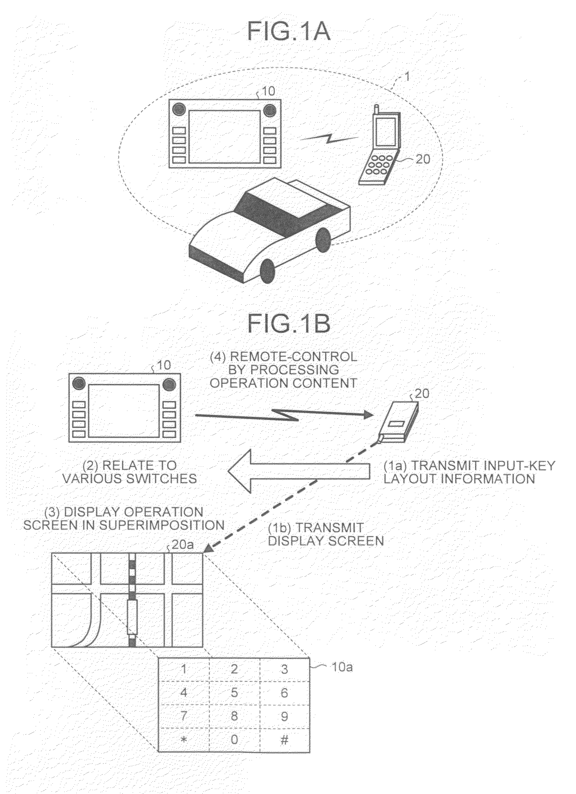
[0044]FIGS. 1A and 1B are schematic diagrams of a remote control system 1 according to the present invention. FIG. 1A depicts devices constituting the remote control system 1, and FIG. 1B depicts an outline of a process performed by the remote control system 1.

[0045]As illustrated in FIG. 1A, the remote control system 1 includes an in-vehicle device 10 having a customizable “virtual switch” displayed on a touch panel display and a “hardware switch” such as a button and a dial, and a portable terminal device 20 such as a mobile telephone carried by an occupant. The in-vehicle device 10 and the portable terminal device 20 are linked with each other by the short-distance wireless communication function such as Bluetooth.

[0046]When a communication link between the in-vehicle device 10 and the portable terminal device 20 is established, the portable terminal device 20 transmits input-key layout information including a layout of input keys to the in-vehicle device 10 as illustrated in FIG...

second embodiment

[0127]An outline of a remote control system is explained first. This remote control system achieves multifunction in linkage with a portable terminal device while having only basic functions in an in-vehicle device among functions incorporated in a vehicle, and causes the in-vehicle device to remote-control the portable terminal device.

[0128]FIG. 11 is a schematic diagram of the remote control system according to the second embodiment. As illustrated in FIG. 11, a remote control system 2 includes a server device 100 provided by a manufacturer manufacturing portable terminal devices or a carrier as a telecommunication carrier, an in-vehicle device 300 mounted on a vehicle, and a portable terminal device 500 such as a mobile telephone and a personal handyphone system (PHS) held by an occupant of a vehicle.

[0129]In the remote control system 2, for the in-vehicle device 300 to call an output of various applications mounted in the portable terminal device 500, a portable application lin...

third embodiment

[0195]That is, a remote control system 3 causes a portable terminal device 900 to generate a drawing command as an instruction to draw an operation key to be displayed in the touch panel 330, by using information of the non-common operation keys acquired from the server device 100. The remote control system 3 causes an in-vehicle device 700 to draw the operation key to be displayed in the touch panel 330 according to the drawing command generated by the portable terminal device 900.

[0196]This is explained with reference to FIG. 18. The server device 100 has stored therein in advance non-common operation-key information for each device type of the portable terminal device. The non-common operation-key information is, for example, contents of a command and an image of the non-common operation key. Upon receiving access from the portable terminal device 900 via a public line, the server device 100 receives assignment of a device type of the portable terminal device 900, transmits the ...


PUM


Abstract

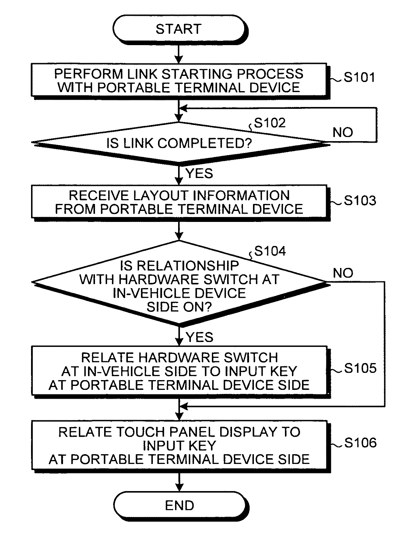
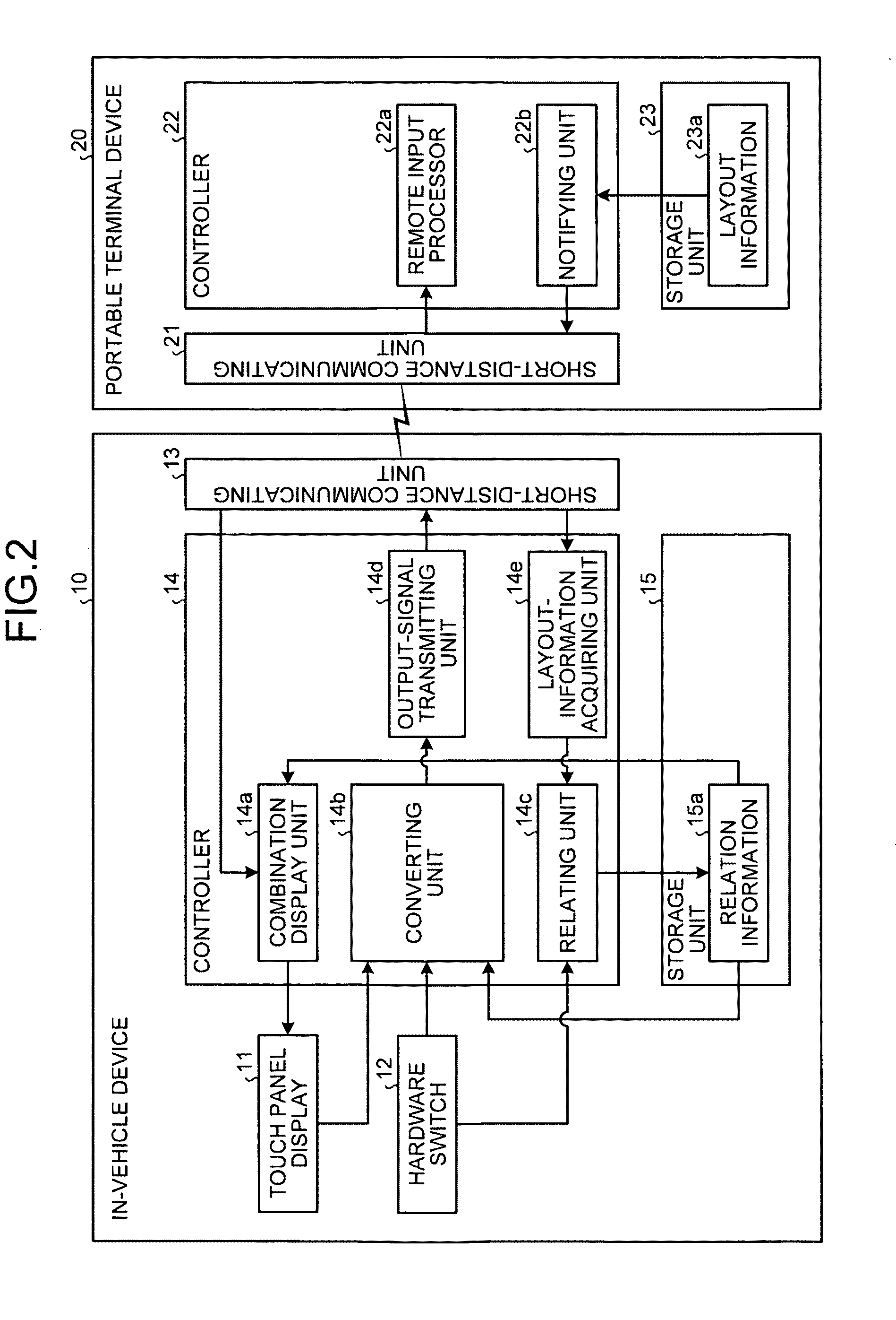
To provide an in-vehicle device including a layout-information acquiring unit, a relating unit, a combination display unit, a converting unit, and an output-signal transmitting unit. The layout-information acquiring unit acquires layout information of input keys of the portable terminal device. The relating unit relates each input key included in the layout information to a predetermined area on a touch panel display. The combination display unit causes a layout screen of each input key related to a predetermined area on the touch panel display to be displayed in the touch panel display. The converting unit converts an input to the touch panel display into an output signal corresponding to a pressing operation of the input key or a combination of the output signals, based on the layout information. The output-signal transmitting unit transmits the output signal obtained by conversion to the portable terminal device.

Description

CROSS-REFERENCE TO RELATED APPLICATIONS[0001]This application is based upon and claims the benefit of priority of the prior Japanese Patent Application No. 2008-303165, filed on Nov. 27, 2008; and Japanese Patent Application No. 2008-305256, filed on Nov. 28, 2008, the entire contents of both of which are incorporated herein by reference.BACKGROUND OF THE INVENTION[0002]1. Field of the Invention[0003]The present invention relates to an in-vehicle device, a remote control system, and a remote control method for remote-controlling a portable terminal device.[0004]2. Description of the Related Art[0005]Along with diffusion of car navigation systems using a global positioning system (GPS), many vehicles come to have in-vehicle devices with a navigation function incorporated therein. To respond to user's desire for multiple functions in in-vehicle devices, in-vehicle devices have become remarkably multifunctional.[0006]For example, in many cases, in-vehicle devices include functions such...

Claims


Application Information

Patent Timeline
Patent Type & Authority Applications(United States)
IPC IPC(8): G06F3/041G06F3/01
CPCG01C21/3688H04M1/6091G06F3/04886
Inventor KITAHARA, TOSHIOOKUDE, KAZUHIROISHIZUKA, YOSHIJI
Owner FUJITSU GENERAL LTD
Learn More