Dual-use sensor assembly for a thermal printer

a sensor and thermal printer technology, applied in the field of thermal printers, can solve problems such as inability to compensate for onsite variability

Active Publication Date: 2010-05-27
KODAK ALARIS INC
View PDF3 Cites 25 Cited by
  • Summary
  • Abstract
  • Description
  • Claims
  • Application Information

AI Technical Summary

Benefits of technology

[0008]Repeatedly measuring the reflected color as the donor web is moving, allows detection of the color patch edges to be positioned for printing. The second position aims the densitometer aperture at the printed receiver, allowing reflection measurements on the printed receiver. A control system is provided to operate the mechanical articulation means, which may include a motor or a solenoid with a spring return, or other convenient method. The mechanical articulation means allow the spring to return the densitometer aperture to position 1 for normal operation including donor movement, and to drive the densitometer aperture to position 2 when required to reflectively measure the density of a completed print.

Problems solved by technology

As this calibration is performed at the factory, there is no means to compensate for onsite variability involving printer usage, media changes and environmental conditions at the customer site.

Method used


Image

  • Dual-use sensor assembly for a thermal printer
  • Dual-use sensor assembly for a thermal printer
  • Dual-use sensor assembly for a thermal printer

Examples


Embodiment Construction

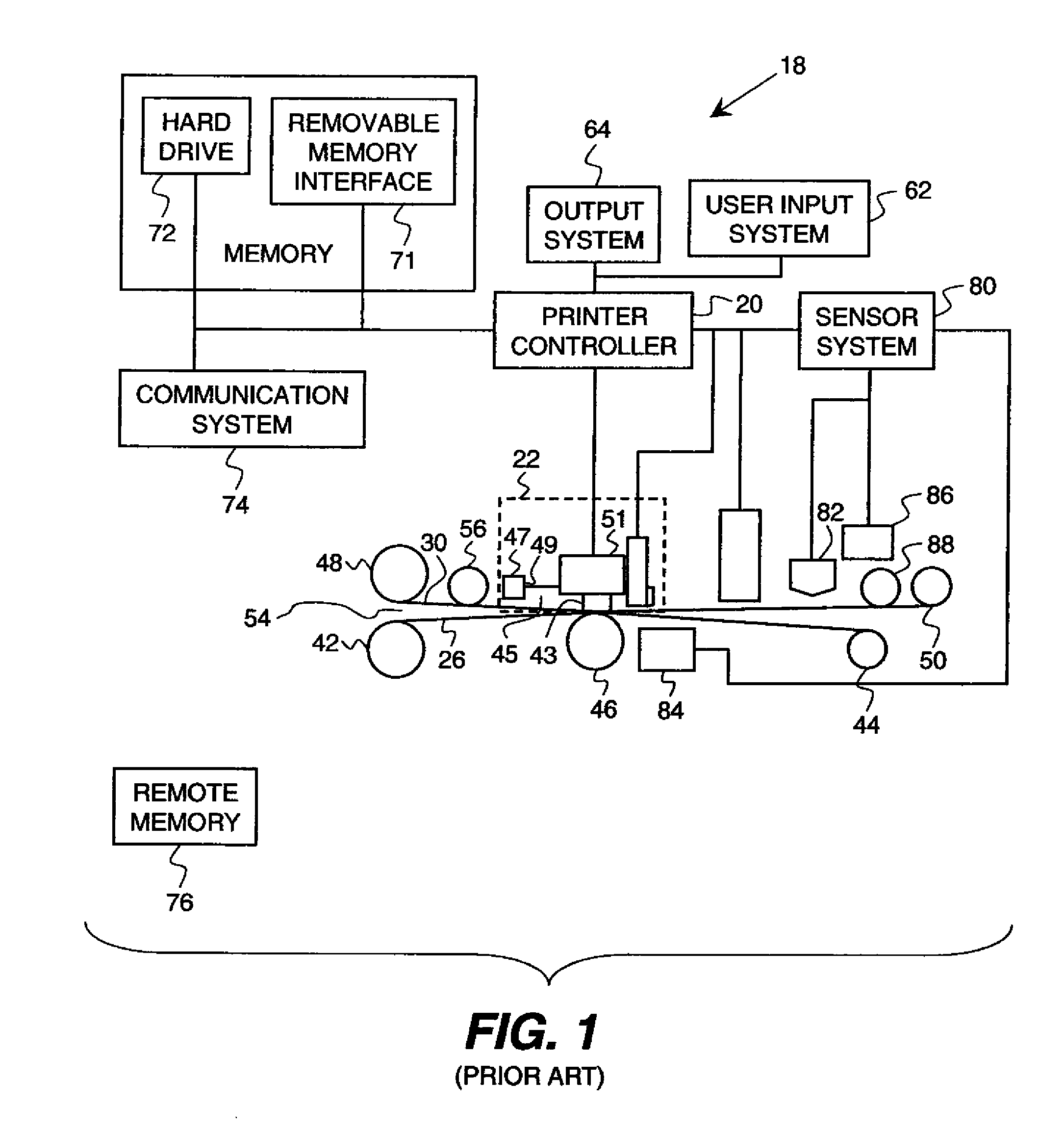
[0021]FIG. 1 shows one embodiment of a conventional thermal printer of the prior art, 18. It shares many of the same features as that of the present invention. As shown in FIG. 1, thermal printer 18 has a printer controller 20 that causes printhead 22 to record images on a receiver medium 26 by applying heat and pressure to transfer material from a donor web 30 to receiver medium 26. Printer controller 20 can include but is not limited to a programmable digital computer, a programmable microprocessor, a programmable logic controller, a series of electronic circuits, a series of electronic circuits reduced to the form of an integrated circuit, or a series of discrete components. In the embodiment of FIG. 1, printer controller 20 also controls a receiver medium take-up roller 42, a receiver medium supply roller 44, a donor web take-up roller 48 and a donor web supply roller 50, which are each motorized for rotation on command of the printer controller 20 to effect movement of receiver...


PUM


Abstract

A sensor apparatus for providing two sensing operations within a thermal printer includes a densitometer with at least one light source that discriminates color and that is positioned in a first position for sensing donor patches within the thermal printer; the densitometer while in a second position provides signals from printed receiver media for internal color calibration of the thermal printer. At least one reflector directs light from the light source to the densitometer through a donor web when the densitometer is in the first position; and a switchable device repositions the densitometer from either the first position or the second position.

Description

FIELD OF THE INVENTION[0001]The present invention relates to thermal printers that record images by transferring donor materials from a donor ribbon to a receiver medium.BACKGROUND OF THE INVENTION[0002]In thermal printing, it is generally well known to render images by heating and pressing one or more donor materials such as dye, colorant or other coating against a receiver medium. The donor materials are provided in sized donor patches on a moveable web known as a donor ribbon. The donor patches are organized on the ribbon into donor patch sets, each donor patch set contains all of the donor patches that are to be used to record an image on the receiver medium. For full color images, multiple colored dye sets can be used, such as yellow, magenta and cyan donor dye patches. Arrangements of other color patches can be used in like fashion within a donor patch set. Additionally, each donor set can include an overcoat or sealant layer.[0003]It will be appreciated from this that it is n...

Claims


Application Information

Patent Timeline
Patent Type & Authority Applications(United States)
IPC IPC(8): B41J2/32
CPCB41J2/36B41J2/325
Inventor EVANS, STUART GERARD
Owner KODAK ALARIS INC
Why Eureka
Try Eureka