Computed tomography method and system

a computed tomography and computed tomography technology, applied in the field of computed tomography method and system, can solve the problems of difficult to accommodate patients with a highly variable heart rate using a conventional axial acquisition mode, difficult to acquire the correct portion of the cardiac cycle axial dataset, and expose the patient to a higher x-ray dos

Active Publication Date: 2010-05-27
GENERAL ELECTRIC CO
View PDF15 Cites 11 Cited by
  • Summary
  • Abstract
  • Description
  • Claims
  • Application Information

AI Technical Summary

Problems solved by technology

However, when acquiring an axial dataset of an anatomical feature experiencing periodic motion, such as the heart, it is a standard practice to only acquire data during a specific portion of the periodic cycle.
For example, it is difficult to accommodate patients with a highly variable heart rate using a conventional axial acquisition mode.
It is also hard to acquire an axial dataset of the correct portion of the cardiac cycle if the patient experiences an irregular heartbeat.
However, since the helical acquisition mode is not prospectively gated, it may result in exposing the patient to a higher x-ray dose than a prospectively gated axial scan of the same anatomic region.

Method used


Image

  • Computed tomography method and system
  • Computed tomography method and system
  • Computed tomography method and system

Examples


Embodiment Construction

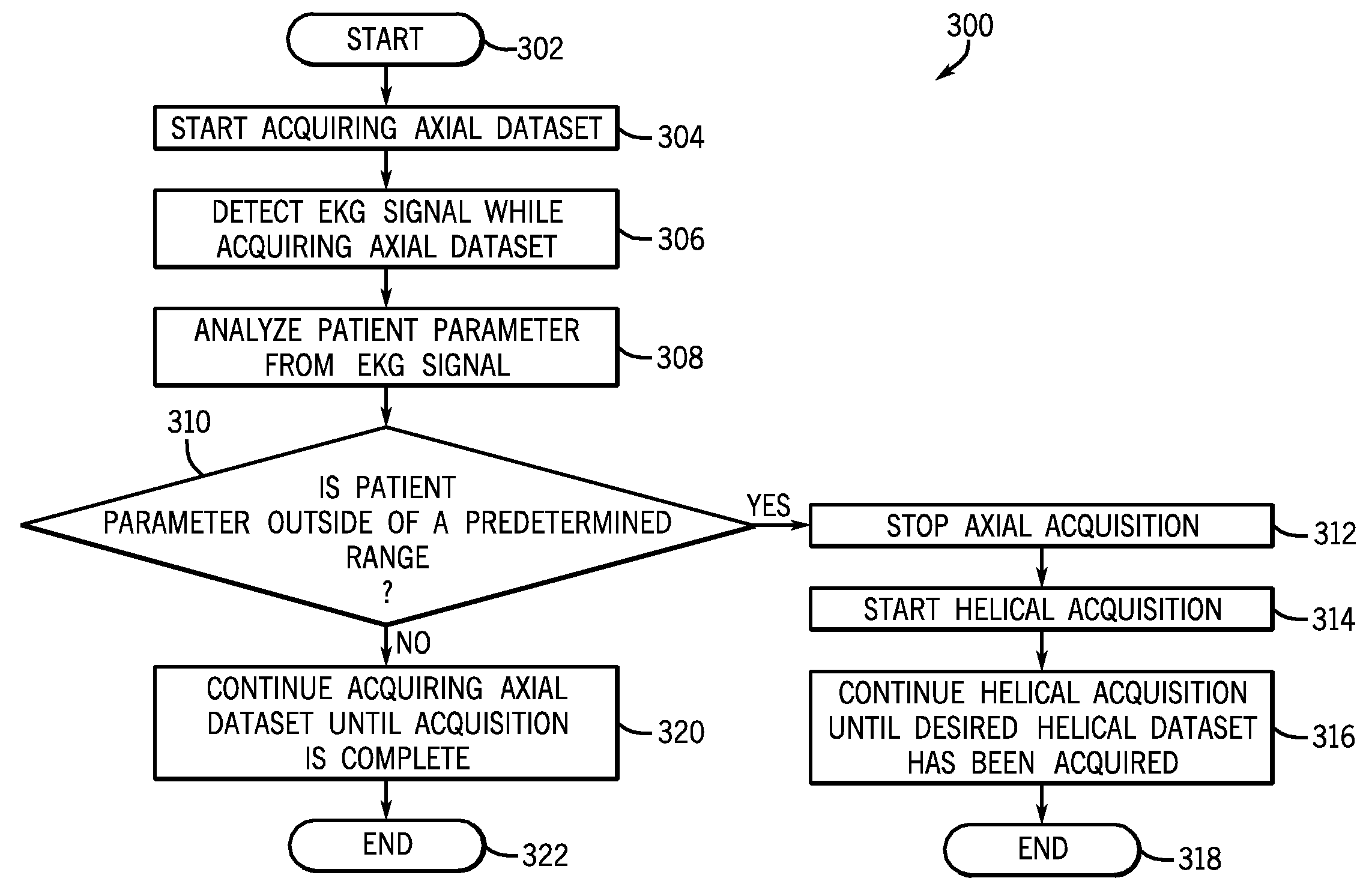
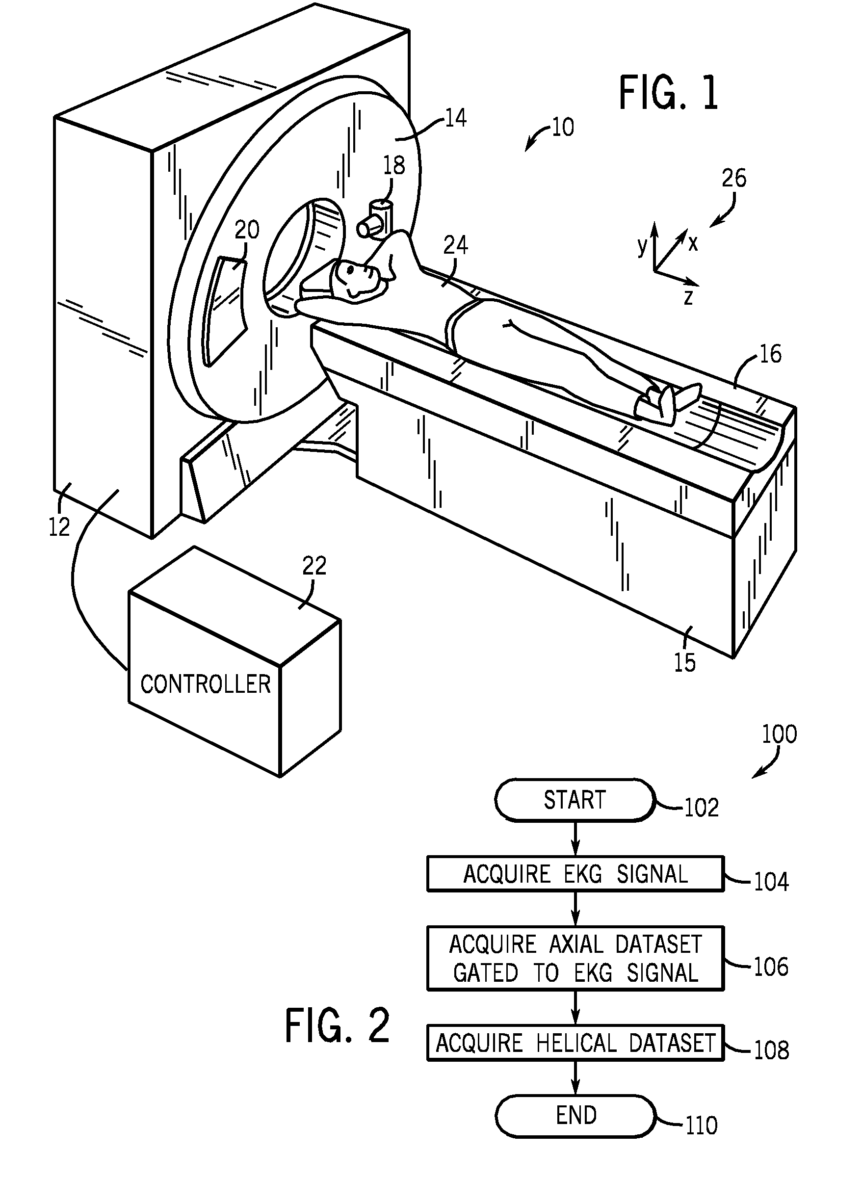
[0018]In the following detailed description, reference is made to the accompanying drawings that form a part hereof, and in which is shown by way of illustration specific embodiments that may be practiced. These embodiments are described in sufficient detail to enable those skilled in the art to practice the embodiments, and it is to be understood that other embodiments may be utilized and that logical, mechanical, electrical and other changes may be made without departing from the scope of the embodiments. The following detailed description is, therefore, not to be taken as limiting the scope of the invention.

[0019]Referring to FIG. 1, a schematic representation of a computed tomography (CT) system 10 according to an embodiment is shown. The CT system 10 includes a gantry support 12, a gantry 14, a table support 15, a table 16, an x-ray tube 18, a detector assembly 20, and a controller 22. The gantry 14 is configured to rotate within the gantry support 12. The gantry 14 is adapted ...


PUM


Abstract

An method of computed tomography is disclosed herein. The method includes acquiring an axial dataset and acquiring a helical dataset as part of an acquisition protocol. A computed tomography system is also disclosed.

Description

FIELD OF THE INVENTION[0001]This disclosure relates generally to a computed tomography method and system.BACKGROUND OF THE INVENTION[0002]Typically, in computed tomography (CT) systems, an x-ray tube emits a fan-shaped x-ray beam or a cone-shaped x-ray beam toward a patient positioned on a table. The x-ray beam, after being attenuated by the patient, impinges upon a detector assembly comprising a plurality of detector elements. The intensity of the attenuated x-ray beam received at the detector assembly is typically dependent upon the attenuation of the x-ray beam by the patient. Each detector element produces a separate electrical signal indicative of the intensity of the attenuated x-ray beam received at that particular detector element.[0003]In known third generation CT systems, the x-ray source and the detector assembly are rotated on a gantry around the object to be imaged so that a gantry angle at which the fan-shaped or cone-shaped x-ray beam intersects the patient constantly...

Claims


Application Information

Patent Timeline
Patent Type & Authority Applications(United States)
IPC IPC(8): A61B6/00G06K9/00
CPCA61B6/032A61B6/481A61B6/504A61B6/027A61B6/541G06T11/003A61B6/5235
Inventor AYALA, RODRIGOHOPPEL, BERNICE E.
Owner GENERAL ELECTRIC CO
Why Eureka
Try Eureka