High Purity Magnetite Formation Process and Apparatus, and Product Thereof

a high-purity magnetite, production process technology, applied in the direction of process and machine control, liquid-gas reaction process, chemical/physical process, etc., can solve the problems of difficult production on a commercial scale, no guidance, flow rate or purity, etc., to achieve simple guidelines, high-purity magnetite

Inactive Publication Date: 2010-05-27
PITTSBURGH IRON OXIDES
View PDF21 Cites 0 Cited by
  • Summary
  • Abstract
  • Description
  • Claims
  • Application Information

AI Technical Summary

Benefits of technology

[0017]It is an object of the present invention to provide a process and a product thereof that includes a specific gas to solids ratio range that allows one to determine the flow rates of the hematite and / or methane into the heating device, thereby providing simple guidelines for achieving high purity magnetite.
[0018]It is another object of the present invention to provide a process and a product thereof that includes a more preferred maximum temperature range of about 750-1200° C. and a most preferred temperature range of about 800-900° C., thereby providing a level of optimum performance.
[0019]It is another object of the present invention to provide a process and a product thereof that includes temperature gradients wherein a maximum temperature is maintained in a second zone and a pre-heating temperature is maintained in a first zone, wherein there is at least one additional zone after the second zone with a temperature lower than that of the second zone, thereby ensuring that the product is not at maximum temperature when exiting the heating device.
[0022]It is a further object of the present invention to provide a scalable process that may be run at high commercial production levels to produce high amounts of high purity magnetite, or may further be downscaled for smaller runs.

Problems solved by technology

No guidance, however, is given as to operating conditions such as gas to solid ratio, flow rates or purity levels
In addition, such processes may require numerous additional steps to perform the reduction properly, which make production on a commercial scale difficult.

Method used


Image

  • High Purity Magnetite Formation Process and Apparatus, and Product Thereof
  • High Purity Magnetite Formation Process and Apparatus, and Product Thereof
  • High Purity Magnetite Formation Process and Apparatus, and Product Thereof

Examples


example 1

[0073]The results of small scale test runs are shown in Table 1. Hematite was fed into a kiln at a rate of 17 pounds per hour. As shown in test runs 1-26 of Table 1, gas was fed into the kiln counter-current to the hematite at a range between 0.071 to 0.223 scfm. The temperature of temperature zone D of the kiln was varied from 700-830° C. The methane was diluted such that 14-50% by volume of the outlet gas was methane. The table shows analysis of the purity of final magnetite products of the process after runs 10, 22, 24, 25, and 26. The “Red / Brown” designation indicates that analysis of the resultant product was performed by visual characterization, red=hematite, black=magnetite, red / brown=a mixture.

TABLE 1Summary of Process Conditions / Changes / ResultsCH4 Flow,CH4,Zone D,Run(scfm)(%)(° C.)Product Purity10.07114700NA20.07123720Red / Brown30.10921720Red / Brown40.10927720Red / Brown50.10930740Red / Brown60.10929740Red / Brown70.10930740Red / Brown80.10928740Red / Brown90.10927740Red / Brown100.10927...

example 2

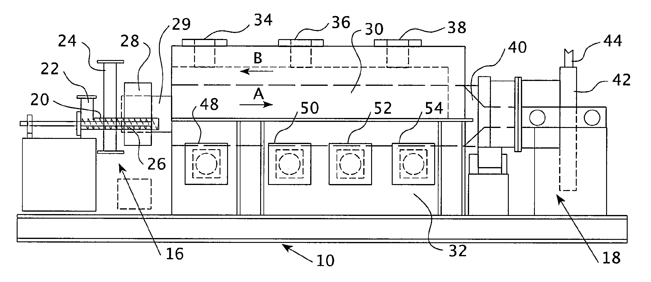
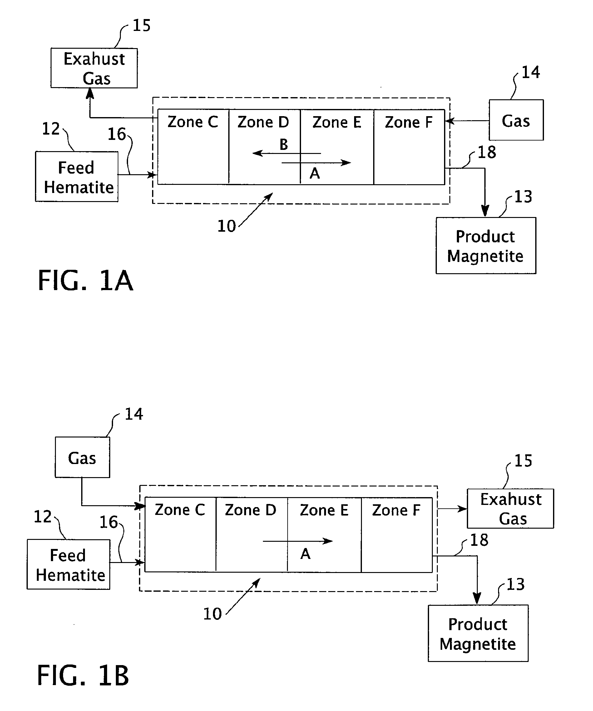
[0076]A kiln was heated such that the maximum temperature of the kiln was 750° C. About 100 kmol of hematite (Fe2O3), or 15,969 kg of hematite, was conveyed into the entry point of the kiln for movement therethrough. Gas was added to the kiln in counter-current flow to the hematite, moving from the exit point of the kiln to the entry point, wherein the gas was about 50% methane and 50% nitrogen. The gas was added over a range of weights, from 0 kmol of methane up to about 25 kmol of methane. At this high end, the 25 kmol of methane is equivalent to 560,350 standard liters of methane, or 19,789 standard cubic feet, assuming an ideal gas.

[0077]As shown in FIG. 7, the full conversion of hematite to magnetite occurs at about 8 kmol of methane and lasts until about 14 kmol of methane are used, at which point wuestite (FeO), a contaminant, begins to be additionally formed. However, it was found that reduction at this level was kinetically poor, such that the reaction tended to happen slow...

example 3

[0078]A kiln was heated such that the maximum temperature of the kiln was 800° C. About 100 kmol of hematite (Fe2O3), or 15,969 kg of hematite, was conveyed into the entry point of the kiln for movement therethrough. Gas was added to the kiln in counter-current flow to the hematite, moving from the exit point of the kiln to the entry point, wherein the gas was about 50% methane and 50% nitrogen. The gas was added over a range of weights, from 0 kmol of methane up to about 25 kmol of methane. At this high end, the 25 kmol of methane is equivalent to 560,350 standard liters of methane, or 19,789 standard cubic feet, assuming an ideal gas.

[0079]As shown in FIG. 8, the full conversion of hematite to magnetite occurs at about 8 kmol of methane and lasts until about 14 kmol of methane are used, at which point wuestite (FeO), a contaminant, begins to be additionally formed. The kinetics of the reaction were more favorable here and in the below examples, and the reduction took place at an a...


PUM

PropertyMeasurementUnit
temperatureaaaaaaaaaa
temperaturesaaaaaaaaaa

Abstract

A process of producing magnetite with a high purity of greater than 90% magnetite, more typically greater than 98% magnetite, by reducing powdered hematite into magnetite under maximum temperatures of about 700 to 1300° C. against a counter-current of or concurrent with methane or natural gas in a heating device. The amount of methane used to reduce the hematite may be about 0.18 and 1.8 standard cubic feet of methane per pound of hematite. A product of high purity methane produced from the process is also provided, where the magnetite is below 1 μM in diameter and has a magnetic saturation greater than 90.0 emu / g. Corresponding apparatus using an improved feeder system for powdered hematite is provided.

Description

BACKGROUND OF THE INVENTION[0001]1. Field of the Invention[0002]The present invention generally relates to a process for producing high purity magnetite from hematite, and a high purity magnetite product formed from the process thereof. Specifically, the invention relates to a process of reducing powdered hematite into magnetite with methane or natural gas, wherein the hematite is reduced in a heating device by a counter-current or concurrent flow of the methane or natural gas, while holding the solids for a specific time at a temperature to effect the reduction to magnetite. The invention further relates to a heating device for performing the method of the invention.[0003]2. Description of the Prior Art[0004]It has been known for many years to convert hematite, composition Fe2O3, into magnetite, composition Fe3O4. Synthetic hematite is a basic reddish brown iron mineral frequently obtained as a byproduct during hydrochloric acid regeneration in operations using this acid to clean o...

Claims


Application Information

Patent Timeline
Patent Type & Authority Applications(United States)
IPC IPC(8): F27B15/00C01G49/08F27B7/20F27B7/42F27B7/34F27B19/02
CPCC01G49/08F27D99/0033F27B9/2423C01P2006/80Y02P10/143
Inventor NICKELS, DALE L.SAWAYDA, MICHAEL E.WEYAND, THOMAS E.
Owner PITTSBURGH IRON OXIDES
Why Eureka
Try Eureka