
Method and Apparatus for Detecting a Two Dimensional Data Matrix

a two-dimensional data and matrix technology, applied in ticket-issuers, sensing record carriers, marketing, etc., can solve the problems of inability to accurately read barcodes using conventional scanning techniques, inability to provide a limited number of one-dimensional barcodes, and inability to accurately detect two-dimensional barcodes from mobile screens, etc., to achieve efficient use of available pixels, increase efficiency in space, and efficient use

Inactive Publication Date: 2010-05-27
PEACHINC
View PDF14 Cites 36 Cited by
  • Summary
  • Abstract
  • Description
  • Claims
  • Application Information

AI Technical Summary

Benefits of technology

[0010]It is therefore an object of the invention to provide a method and apparatus which can read data which is encoded and displayed in a way which makes efficient use of the space available, whilst still enabling the location and orientation of a printed or displayed barcode to be determined by the barcode reading method and apparatus. Furthermore, it is desirable to provide a method and apparatus in which a barcode can be reliably read from an electronic display.
[0020]By using predetermined locating patterns or symbols at predetermined positions within the matrix, for example two locating symbols at opposite diagonal corners of the matrix, a relatively small number of cells are taken up in defining the location and orientation of the matrix. In particular, the same locating patterns can be used in at least two of the corners of the matrix, regardless of the overall size of a given matrix. This means that a larger matrix can be used if more data is required to be stored, but the number of cells dedicated to the locating patterns can remain the same. By contrast, with a conventional two dimensional barcode system in which a black border is required on at least two sides of the pattern, together with a further white border surrounding the entire barcode, the number of cells used for this location and orientation function will increase as the size of the matrix increases. The described arrangement therefore provides a more efficient utilisation of the available pixels than this conventional arrangement, as the size of the matrix increases, and can also be used without a ‘quiet zone’, such that the screen area of a mobile device can be more efficiently utilised, or in a printed application, for example, other printed material may appear directly adjacent to the data cells of the matrix.
[0021]The locating symbols may be predetermined independently of the size of the bar code pattern, such that the step of identifying potential occurrences of the locating symbol(s) within the image is carried out independently of the size of the bar code pattern. In this way, the same locating symbols can be used for different sizes of bar code pattern, leading to increased efficiency in the space taken up by the locating symbol(s), as the size of the bar code pattern increases.
[0022]The matrix may include check cells, which are used to verify the correct reading of the pattern. In particular, the check cells may include at least one of: column parity check cells; row parity check cells; and data region sum check cells, and may include all three of these check systems, whereby to allow the use of very simple and space efficient locating symbols whilst also sufficiently reducing the occurrence of false positive readings.

Problems solved by technology

In this type of application in particular, it has been found that a one dimensional barcode can only provide a limited number of unique identifiers, due to the restricted screen size on a mobile device, and conventional two dimensional barcodes can be difficult to read from a mobile screen.
Although a larger number of pixels can be displayed with increasing screen resolution, the resulting barcodes can be too small to be accurately read using conventional scanning techniques.
Furthermore, the size of barcode which can be transmitted to a mobile phone is generally limited by the relevant messaging protocols.
Furthermore, with particular reference to barcodes displayed on electronic screens, problems arise with reading barcodes using conventional barcode scanners, due to the surface of the screen often being highly reflective, making it difficult to read the displayed image in certain conditions.
Furthermore, the screen of a mobile device such as a telephone is more likely to be scratched or wet, leading to reading errors.
Some systems use elaborate locator patterns, which may reduce number of false positive readings, but many of these use too much space to be used on a mobile device screen or other area with limited space, e.g. in SMS / EMS messages.

Method used


Image

  • Method and Apparatus for Detecting a Two Dimensional Data Matrix
  • Method and Apparatus for Detecting a Two Dimensional Data Matrix
  • Method and Apparatus for Detecting a Two Dimensional Data Matrix

Examples


Embodiment Construction

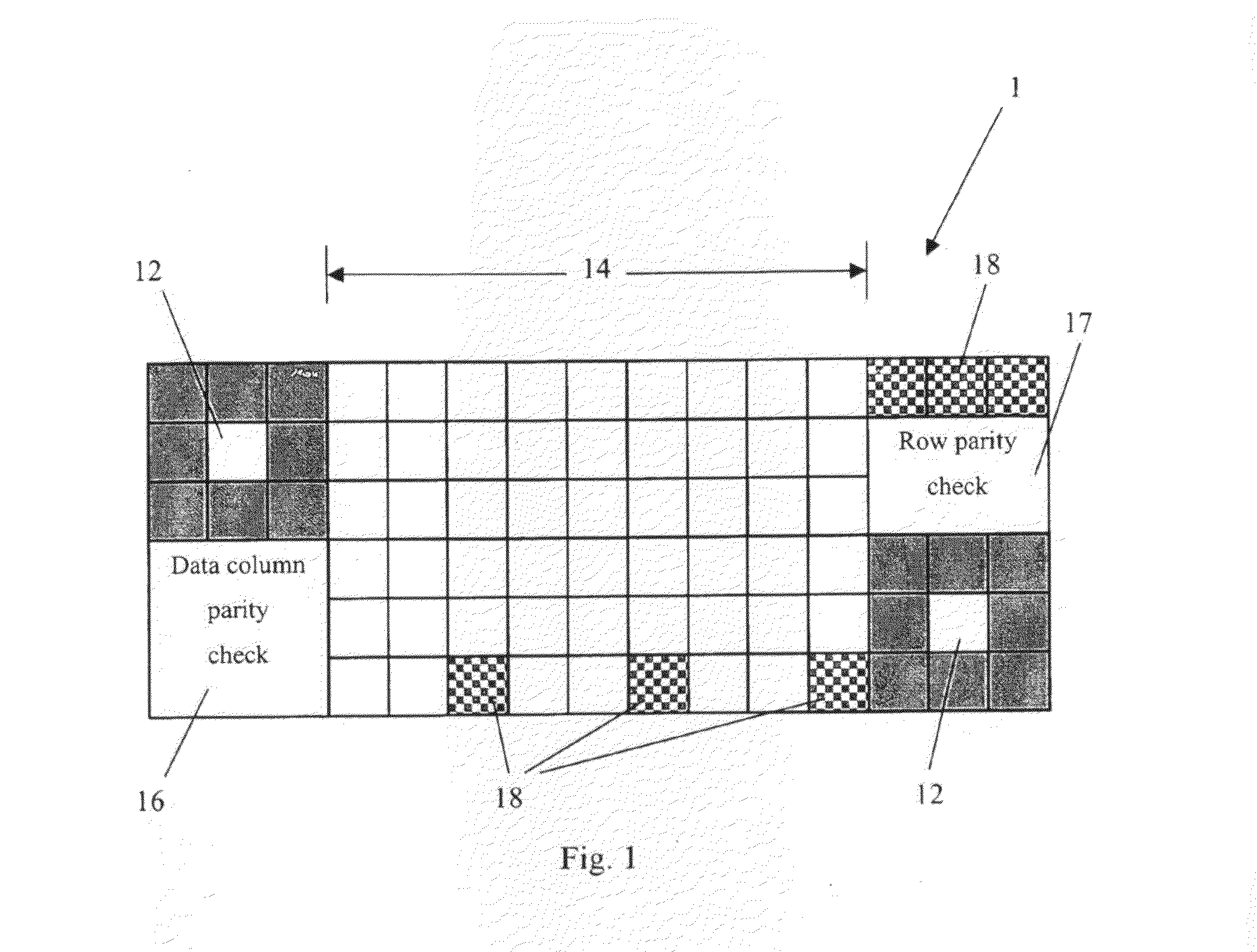
[0029]FIG. 1 illustrates an example of a data matrix used in one embodiment of the invention. In this case, the matrix is a 15×6 pattern of cells, although other formats and sizes may be used. It should also be noted that the term ‘cell’ is used here to describe the smallest data portion of the pattern, which may be either black or white in this example, representing different binary data values (or may use other combinations of colours and / or greyscales in other examples), and therefore corresponds to a data pixel in a conventional two dimensional barcode. However, it should be appreciated that a cell may in fact be made up of more than one actual pixel of a display screen, such as a mobile phone screen. In particular, when the matrix is displayed on a mobile phone or similar device, the use of, for example, four or sixteen screen pixels to display each cell (i.e. a 2×2 or 4×4 block of pixels) ensures that the resulting image is large enough to be accurately read. Nevertheless, on ...


PUM


Abstract

A method for detecting a two-dimensional bar code pattern using a bar code pattern reader, the bar code pattern being in the form of a matrix of rows and columns of data cells of either a first or second colour representing encoded data bits, and containing a set of at least two predetermined locating symbols at predetermined positions within the bar code pattern, wherein the method comprises the steps of: receiving a two-dimensional image containing the pattern, analysing the image to identify potential occurrences of the locating symbols within the image, validating the potential occurrences of locating symbols by analysing the potential occurrences to identify any set of occurrences whose size and relative positions within the image are consistent with the predetermined positions of the locating symbols within the bar code pattern, thereby identifying a set of locating symbols, and identifying the location of the bar code pattern within the image on the basis of the positions of the identified locating symbols. An apparatus for carrying out the method, and systems which utilise the bar code pattern, are also disclosed.

Description

[0001]The invention relates to the coding and decoding of information recorded in the form of a two dimensional barcode, or data matrix, the information being represented in the form of a grid of rows and columns of data cells. In particular, the invention relates to a method and apparatus for detecting and reading such recorded data, which may be displayed on any medium, but in particular for reading the data when displayed on a screen of an electronic device such as a mobile phone or personal digital assistant (PDA). The invention also relates to systems which utilise a transmittable two dimensional data matrix.[0002]Conventional one dimensional barcodes are well known, and comprise a strip of parallel lines of differing widths to represent numerical values, thereby providing a numerical identifier which may be read using simple scanning technologies. Typical scanners operate by emitting a laser onto the surface provided with the barcode, and reading the light reflected from the s...

Claims


Application Information

Patent Timeline
IPC IPC(8): G06K7/00G06K7/14G06Q30/00G06Q40/00G06Q30/02
CPCG06K7/14G06Q30/0268G06K7/1456G06K7/1443G06K19/06037G07B15/00H04W4/14G06V10/457
Inventor MORRIS, DANIELMANTOCK, PETER
Owner PEACHINC
Learn More