Method of assembling a pump motor with bearing preload

a technology of bearing preload and pump motor, which is applied in the direction of machines/engines, manufacturing stator/rotor bodies, and positive displacement liquid engines, etc., can solve the problems of motor life appreciably reduced, motors subject to changing internal temperatures, and loss of preload on bearings

Active Publication Date: 2010-06-03
HARGRAVES TECH CORP
View PDF9 Cites 6 Cited by
  • Summary
  • Abstract
  • Description
  • Claims
  • Application Information

AI Technical Summary

Benefits of technology

[0008]A rotor assembly having first and second ends is mounted in the first and second bearings, respectively, such that the rotor has a predetermined amount of axial and radial play relative to the housing. A biasing element is disposed between one of the rotor assembly or the housing and one of the bearings. The biasing element urges the rotor assembly to a preloaded position which eliminates the axial and radial play. Each of the first inner and outer races and the second inner and outer races is secured to one of the rotor assembly or to the housing, such that the rotor assembly is retained in the preloaded position.
[0021]A biasing element is disposed between one of the rotor assembly or the housing and one of the bearings which urges the rotor assembly to a preloaded position which eliminates the axial and radial play. The first inner and outer races are secured to the shaft, and the second inner and outer races are secured to the housing, such that the rotor assembly is retained in the preloaded position.

Problems solved by technology

In an application where the motor is connected to a cyclic load, particularly a radial load (i.e. perpendicular to the motor shaft axis) such as that applied by a diaphragm pump, the interaction of the bearing play with the load may cause the motor life to be appreciably reduced through fatigue, fretting of the motor components, and rapid wear.
However, in operation the motor will be subject to changing internal temperatures, resulting from heat generated by the motor itself or absorbed from the environment in which the motor operates.
This varying thermal expansion may cause the preload on the bearings to be lost, resulting in the accelerated wear described above.
The varying thermal expansion may also cause an excessive axial and / or radial load to be placed on the bearings thus also accelerating wear.

Method used


Image

  • Method of assembling a pump motor with bearing preload
  • Method of assembling a pump motor with bearing preload
  • Method of assembling a pump motor with bearing preload

Examples


first embodiment

[0037]Turning now to the present invention, FIG. 4 shows a motor 10 constructed in accordance with the present invention. The illustrated example is of a brushless permanent magnet DC motor, but the operative principle of the present invention is equally application to other types of motors as well. The basic components of the motor 10 are a housing 12, an end bell 14, a stator 16, a rotor assembly 18, a front bearing 20, a rear bearing 22, and a spring 24. The housing 12 is a generally cylindrical, open-ended member including an axially extending portion 26 and a front end plate 28 which has a front bearing pocket 30 formed therein. The front end plate portion of the housing 12 could also be a separate component attached by a variety of methods, for example, screws, press fit, welding, etc. The housing 12 may be formed by any known method including casting, forging, machining, powder metallurgy, etc. The end bell 14 is a member adapted to close off the rear end of the housing 12 an...

second embodiment

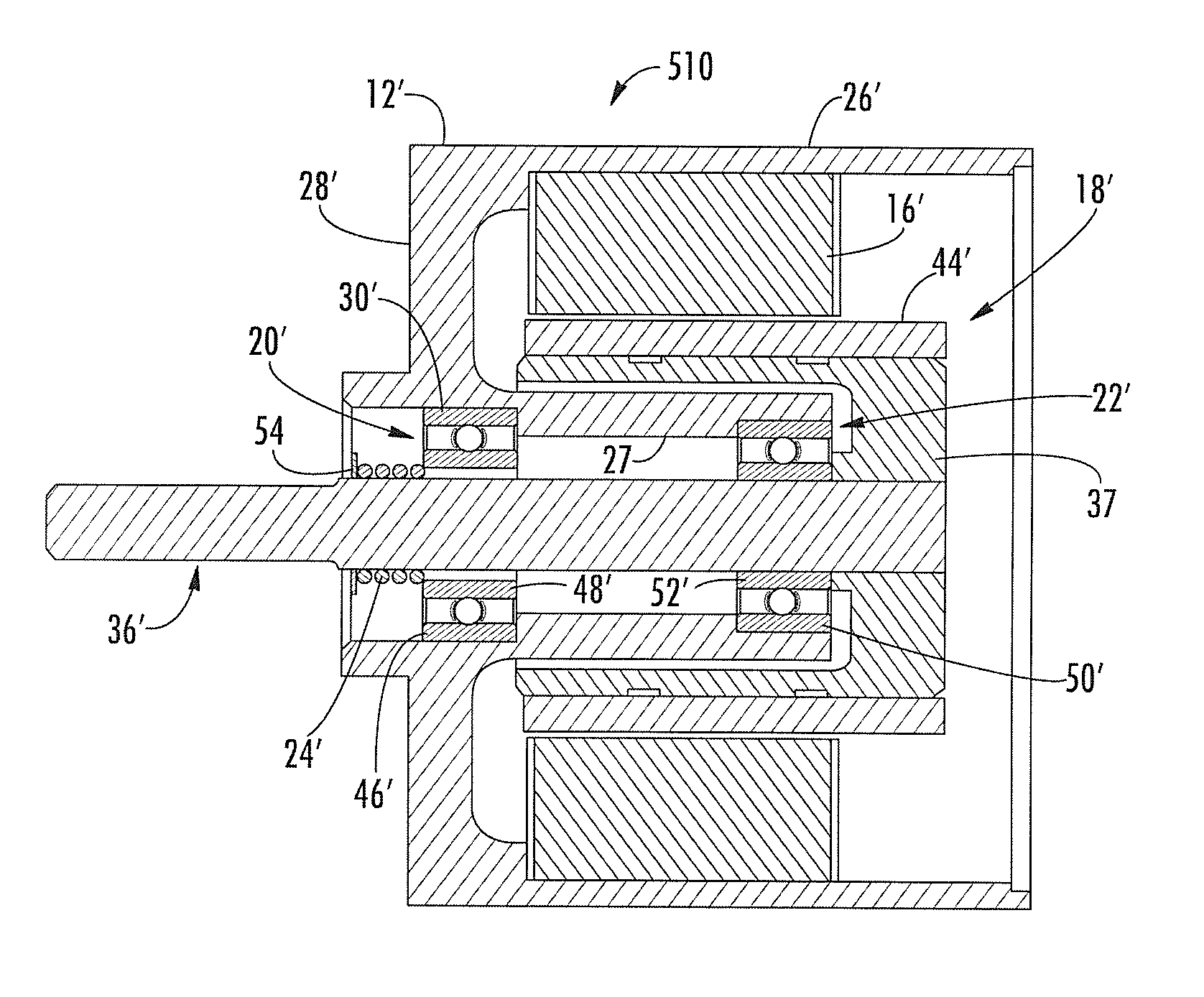
[0048]FIG. 8 shows a motor 410 constructed in accordance with the present invention. This type of motor is sometimes referred to as a cantilevered design because of the relationship of the rotor assembly to the bearings. Elements in common with the motors depicted in FIGS. 4-7 are shown in prime reference numerals. The basic components of the motor 410 are a housing 12′, a stator 16′, a rotor assembly 18′, a front bearing 20′, a rear bearing 22′, and a preload spring 24′. The housing 12′ is a generally cylindrical, open-ended member including outer axially extending portion 26′, an inner axially extending portion 27, and a front end plate 28′. The inner axially extending portion 27 defines a front bearing pocket 30′ and a rear bearing pocket 34′. The housing 12′ may be formed by any known method including casting, forging, machining, powder metallurgy, etc. The stator 16′ is of a known type comprising an array of flat plates wound with coils of wire. The rotor assembly 18′ comprises...


PUM

PropertyMeasurementUnit
temperatureaaaaaaaaaa

Abstract

A non-reciprocating motor adapted for driving a reciprocating load is assembled by selecting a housing, a first bearing, a second bearing, and a rotor assembly having a shaft, all having corresponding predetermined coefficients of thermal expansion. The first and second bearings are positioned in the housing. The rotor assembly is rotatably mounted in the housing with the shaft received in the first and second bearings, such that the rotor is in a first position in which it has a predetermined amount of axial and radial play relative to the housing. A biasing element is installed and forces the rotor assembly to a second position in which play is eliminated. Each race is then permanently secured such that the rotor assembly is retained in the second position over a temperature range of about minus 40 degrees to about 105 degrees Celsius.

Description

CROSS REFERENCE TO RELATED APPLICATIONS[0001]This non-provisional patent application is a continuation of, and claims the full benefit of priority of, U.S. non-provisional patent application Ser. No. 10 / 550,256, which is entitled “Pump Motor with Bearing Preload” and is currently pending. The Ser. No. 10 / 550,256 application is a non-provisional application that completed 35 U.S.C. 371 requirements on Sep. 22, 2005, and represents the U.S. national stage entry of international application number PCT / US2004 / 011403, which was filed on Apr. 14, 2004, and is entitled “Pump Motor with Bearing Preload.” This application, the Ser. No. 10 / 550,256 application and the PCT / US04 / 11403 application all claim the benefit of priority of U.S. provisional patent application No. 60 / 462,788, which was filed on Apr. 14, 2003, and is entitled “Pump Motor with Bearing Preload.”BACKGROUND OF THE INVENTION[0002]This invention relates generally to electric motors and more particularly to an electric motor int...

Claims


Application Information

Patent Timeline
Patent Type & Authority Applications(United States)
IPC IPC(8): H02K15/02F04B17/03F16C25/08H02K5/173
CPCF04B17/03F16C25/08H02K5/1732Y10T29/49679Y10T29/49009Y10T29/49698Y10T29/49012H02K5/1735F16C19/06F16C25/083
Inventor HARGRAVES, DONALD EDWINCURTIS, DOUGLAS ALLAN
Owner HARGRAVES TECH CORP
Why Eureka
Try Eureka