Mechanically driven centrifugal pyrolyzer

a centrifugal pyrolysis and mechanical drive technology, applied in the direction of soldering apparatus, manufacturing tools, combustion gas production, etc., to achieve the effect of mitigating disadvantages and shortcomings

Inactive Publication Date: 2010-06-03
GAS TECH INST
View PDF8 Cites 12 Cited by
  • Summary
  • Abstract
  • Description
  • Claims
  • Application Information

AI Technical Summary

Benefits of technology

[0008]It is, thus, one object of this invention to provide an ablative pyrolysis apparatus and meth...

Problems solved by technology

However, at no time is any direct radial force applied by the bl...

Method used


Image

  • Mechanically driven centrifugal pyrolyzer
  • Mechanically driven centrifugal pyrolyzer
  • Mechanically driven centrifugal pyrolyzer

Examples


Embodiment Construction

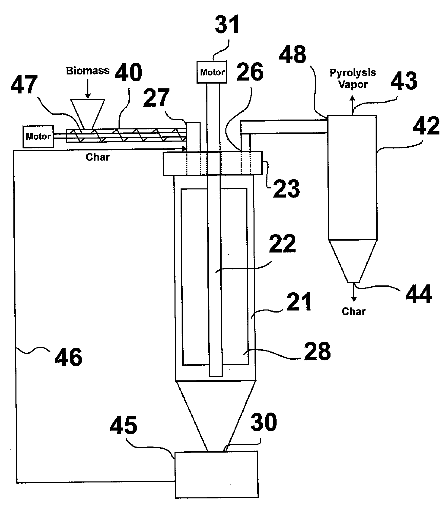
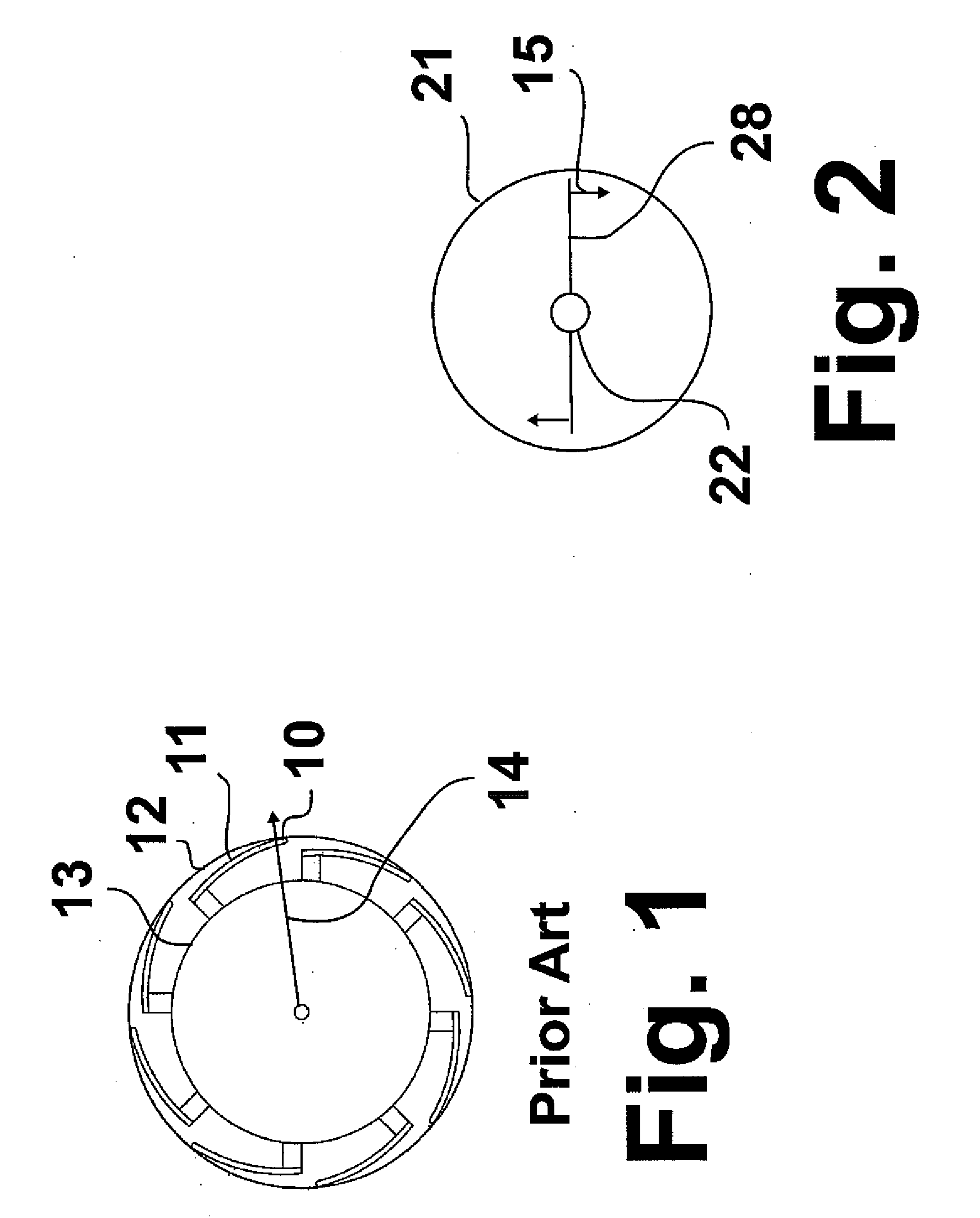
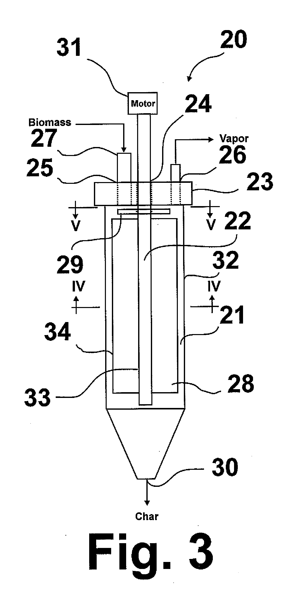
[0017]The invention claimed herein is an ablative pyrolyzer 20 for fast pyrolysis of biomass and other solid organic materials as shown in FIG. 3 comprising a vertically oriented cylindrical pyrolyzer vessel 21 having a solids outlet 30 proximate the bottom thereof, a vapor outlet 26, a top wall 23 forming at least one opening, and an adjacent heated side wall 32. Although this invention will be described with reference to biomass feedstock, it is to be understood that the invention is suitable for use with any solid organic-based material able to undergo pyrolysis, and such uses are deemed to be within the scope of this invention. Disposed within the cylindrical vessel and extending through opening 24 is a rotor comprising rotatable shaft 22 coincident with the longitudinal axis of the cylindrical vessel. Rotatable shaft motor 31 is operably connected with the rotor for rotating rotatable shaft 22. At least one blade or paddle 28 is connected directly or indirectly, i.e. using inte...


PUM


Abstract

An apparatus for fast pyrolysis of biomass and other solid organic materials including a vertically oriented cylindrical vessel having a solids outlet proximate the bottom thereof, a vapor outlet, a top wall forming at least one opening, and an adjacent heated side wall. Disposed within the cylindrical vessel and extending through the at least one opening in the top wall is a rotor having a rotatable shaft coincident with the longitudinal axis of the cylindrical vessel to which is attached at least one substantially vertically oriented blade having one edge connected directly or indirectly with the rotatable shaft and having an opposite edge spaced apart from the heated side wall, whereby a non-radial, preferably tangential, force is imparted on the feedstock in the cylindrical vessel. Also disclosed is a method for fast pyrolysis of biomass and other solid organic materials.

Description

[0001]The U.S. Government has a paid-up license in this invention and the right in limited circumstances to require the patent owner to license others on reasonable terms as provided for by the terms of Contract No. DE-FG36-01GO11082 awarded by the U.S. department of Energy.BACKGROUND OF THE INVENTION[0002]1. Field of the Invention[0003]This invention relates to a method and apparatus for ablative pyrolysis of biomass to form condensable liquid products having properties, such as viscosity and energy density, that make the products useful as fuel oil, or as a source of chemicals, or for the production of chemicals and / or derived products.[0004]2. Description of Related Art[0005]In general, pyrolysis is a chemical process in which a compound (feedstock) is converted to one or more products by heat. Most pyrolysis processes utilize heat transfer from a hot gas and / or hot solid, such as sand, to the feedstock and rely upon the particles of the feedstock being small to achieve rapid hea...

Claims


Application Information

Patent Timeline
IPC IPC(8): C10J3/62
CPCC10B7/02Y02E50/14C10C5/00C10B53/02Y02E50/10Y02P20/145
Inventor LINCK, MARTIN BRENDANBUSH, PHILLIP VANN
Owner GAS TECH INST
Why Eureka
Try Eureka