Fabricated itd-strut and vane ring for gas turbine engine

Inactive Publication Date: 2010-06-03
PRATT & WHITNEY CANADA CORP
View PDF55 Cites 80 Cited by
  • Summary
  • Abstract
  • Description
  • Claims
  • Application Information

AI Technical Summary

Problems solved by technology

It is a challenge in design to meet both aero and structural requirements, yet all the while providing a low cost, low weight design, to name but a few concerns, especially in aero applications.

Method used


Image

  • Fabricated itd-strut and vane ring for gas turbine engine
  • Fabricated itd-strut and vane ring for gas turbine engine
  • Fabricated itd-strut and vane ring for gas turbine engine

Examples


Embodiment Construction

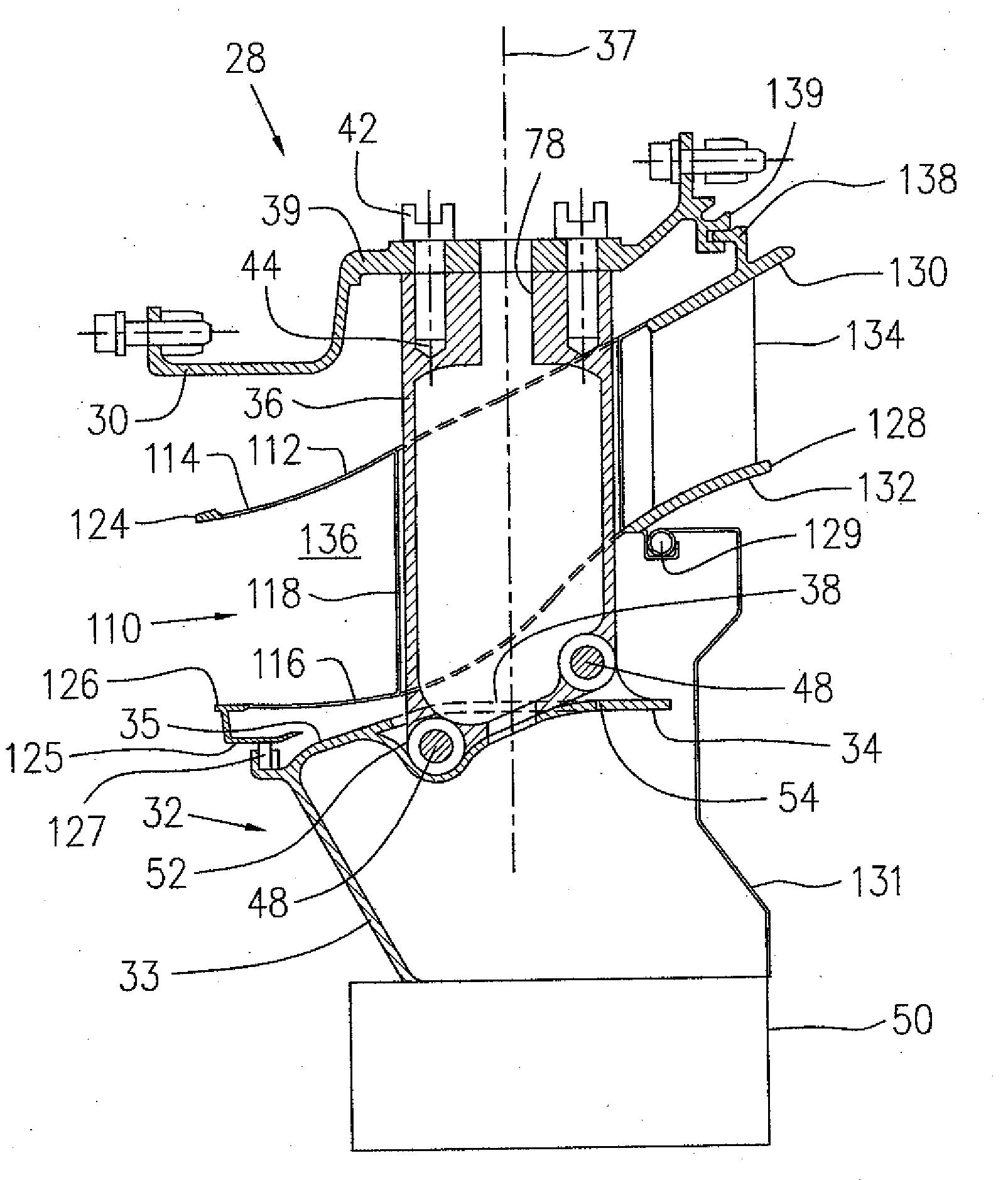
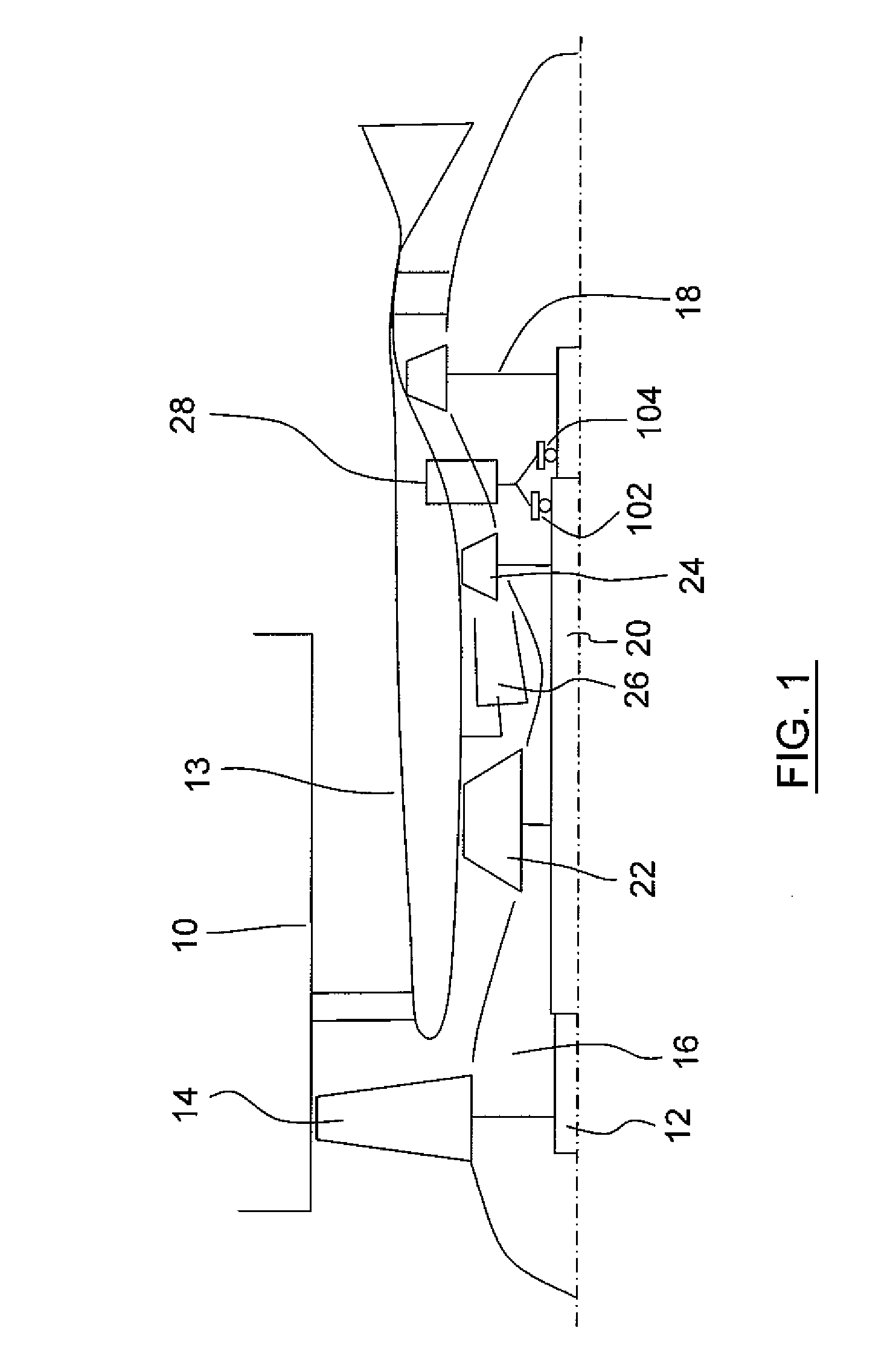
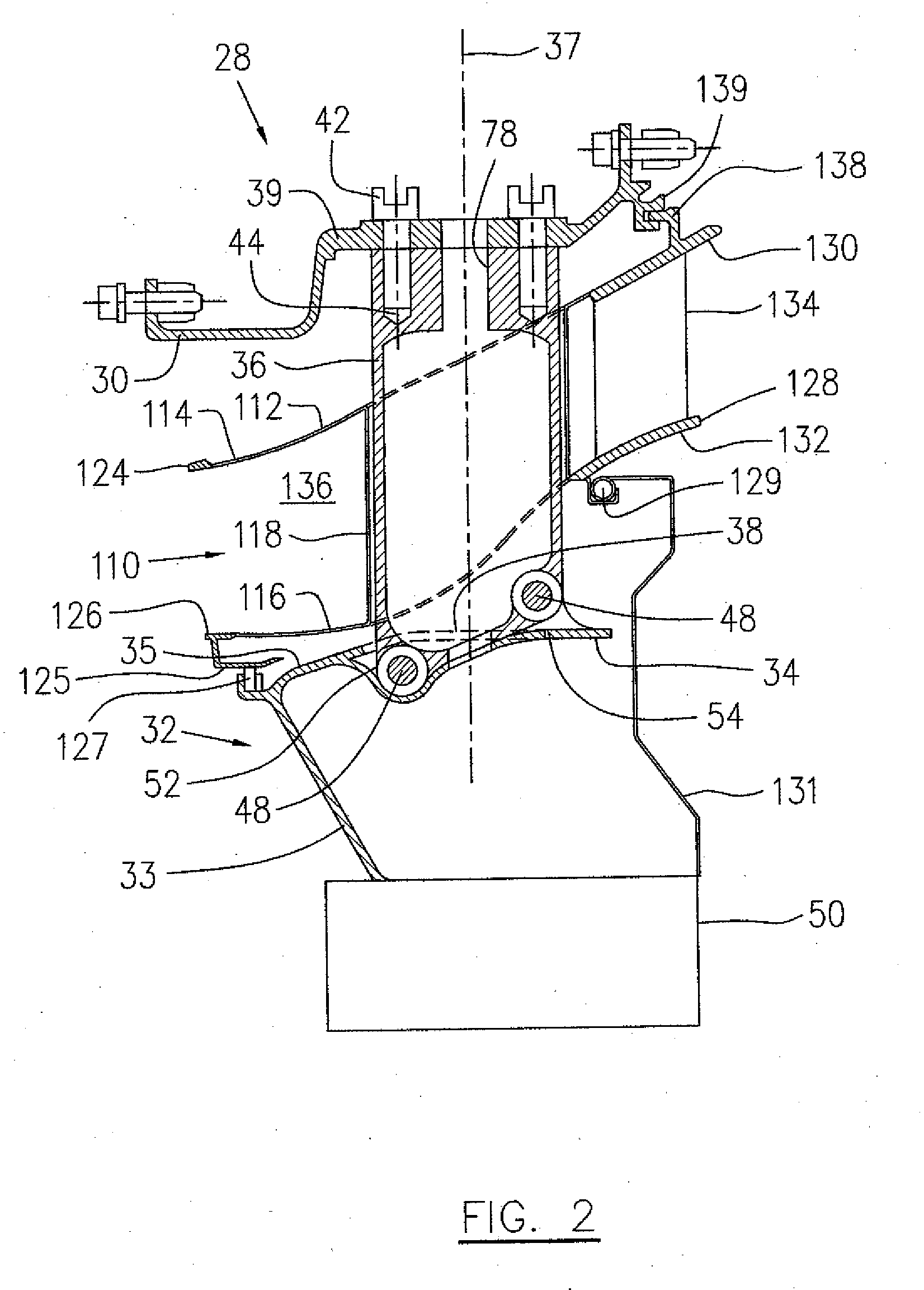
[0017]Referring to FIG. 1, a turbofan gas turbine engine includes a fan case 10, a core case 13, a low pressure spool assembly which includes a fan assembly 14, a low pressure compressor assembly 16 and a low pressure turbine assembly 18 connected by a shaft 12, and a high pressure spool assembly which includes a high pressure compressor assembly 22 and a high pressure turbine assembly 24 connected by a turbine shaft 20. The core casing 13 surrounds the low and high pressure spool assemblies to define a main fluid path therethrough. In the main fluid path there is provided a combustor 26 to generate combustion gases to power the high pressure turbine assembly 24 and the low pressure turbine assembly 18. A mid turbine frame system 28 is disposed between the high pressure turbine assembly 24 and the low pressure turbine assembly 18 and supports bearings 102 and 104 around the respective shafts 20 and 12. The terms “axial”, “radial” and “tangential” used for various components below, a...


PUM

PropertyMeasurementUnit
pressureaaaaaaaaaa
weightaaaaaaaaaa
pressure lossaaaaaaaaaa

Abstract

A gas turbine engine mid turbine frame having an annular interturbine duct and vane ring assembly includes a duct having outer and inner duct walls of sheet metal interconnected by radial hollow struts of sheet metal and a vane ring is connected to the duct to provide the assembly. The interturbine duct and vane ring assembly may be provided within a mid turbine frame in a manner which is independent of a bearing load path through the mid turbine frame.

Description

TECHNICAL FIELD[0001]The application relates generally to gas turbine engines and more particularly, to a fabricated ITD-strut vane ring therefore.BACKGROUND OF THE ART[0002]A gas turbine engine typically has at least a high pressure turbine stage and a low pressure turbine stage, and the gas path between the two is often referred to as an interturbine duct (ITD). The function of the ITD is to deliver combustion gases from the high to low turbine stage. Along the way, there is usually a stage of stationary airfoil vanes. In larger engines, ITDs are often incorporated into a frame configuration, such as a mid turbine frame (MTF), which transfers bearing loads from a main shaft supported by the frame to the engine outer case. Conventional ITDs are cast with structural vanes which guide combustion gases therethrough and transfer structural loads. It is a challenge in design to meet both aero and structural requirements, yet all the while providing a low cost, low weight design, to name...

Claims


Application Information

Patent Timeline
Patent Type & Authority Applications(United States)
IPC IPC(8): F02C7/20F01D9/04B23P11/00
CPCF01D9/047Y10T29/4932F01D25/162F01D9/065
Inventor DUROCHER, ERICPIETROBON, JOHN
Owner PRATT & WHITNEY CANADA CORP
Why Eureka
Try Eureka