Piston-side brake shim

a piston rim and shim technology, applied in the direction of slack adjusters, brake types, braking elements, etc., can solve the problems of affecting the lubricating effect of the piston rim, and none of the problems have been entirely satisfactory, so as to prevent lubricant buildup, uniform distribution of lubricant, and better lubricating

a piston rim and shim technology, applied in the direction of slack adjusters, brake types, braking elements, etc., can solve the problems of affecting the lubricating effect of the piston rim, and none of the problems have been entirely satisfactory, so as to prevent lubricant buildup, uniform distribution of lubricant, and better lubricating

US20100133050A1Active Publication Date: 2010-06-03NUCAP IND

Image

  • Piston-side brake shim
  • Piston-side brake shim
  • Piston-side brake shim

Examples


Embodiment Construction

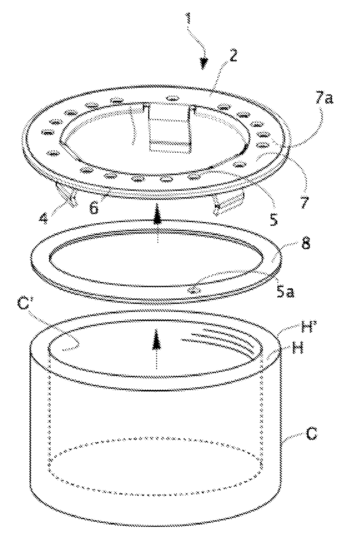
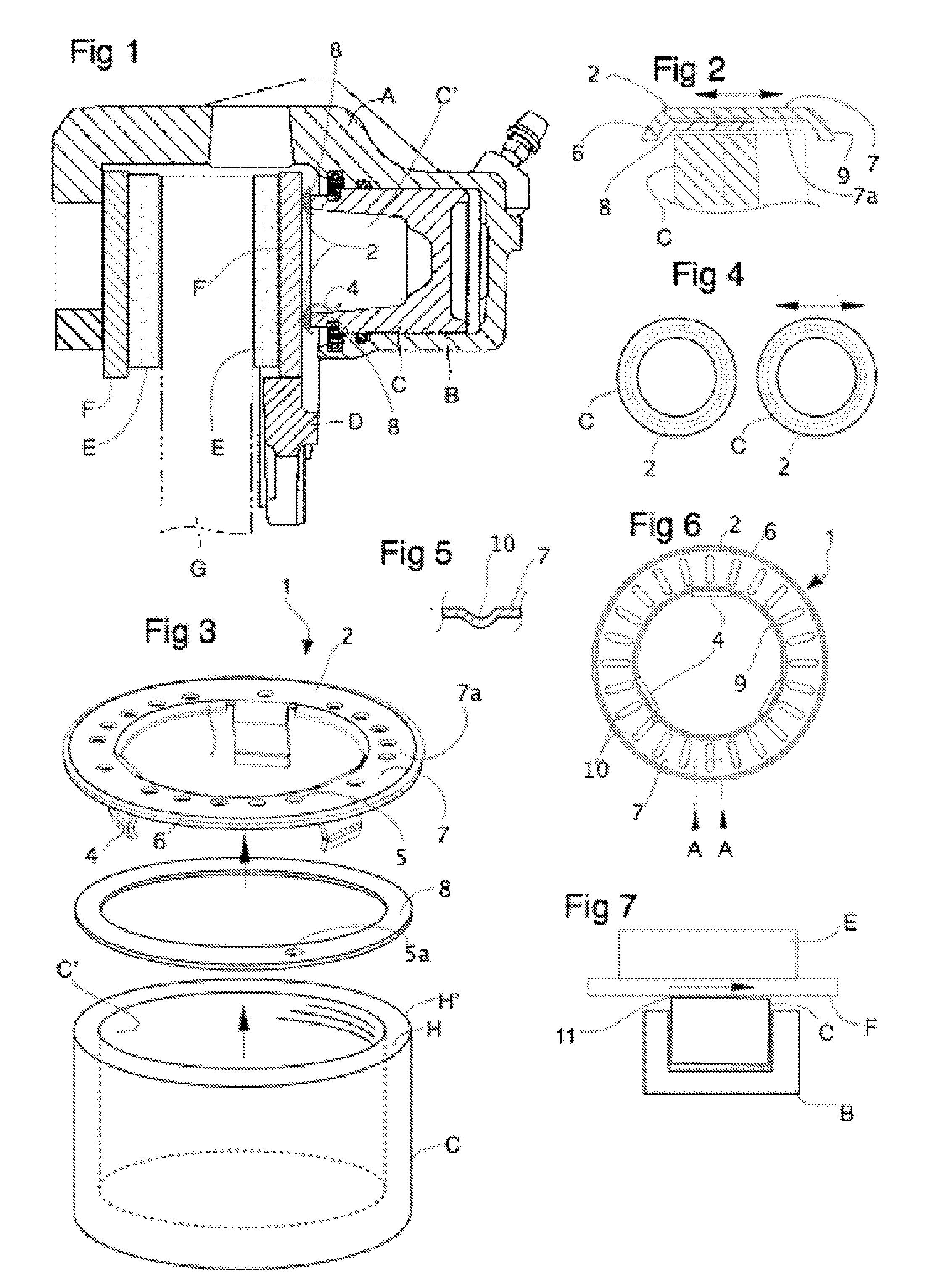
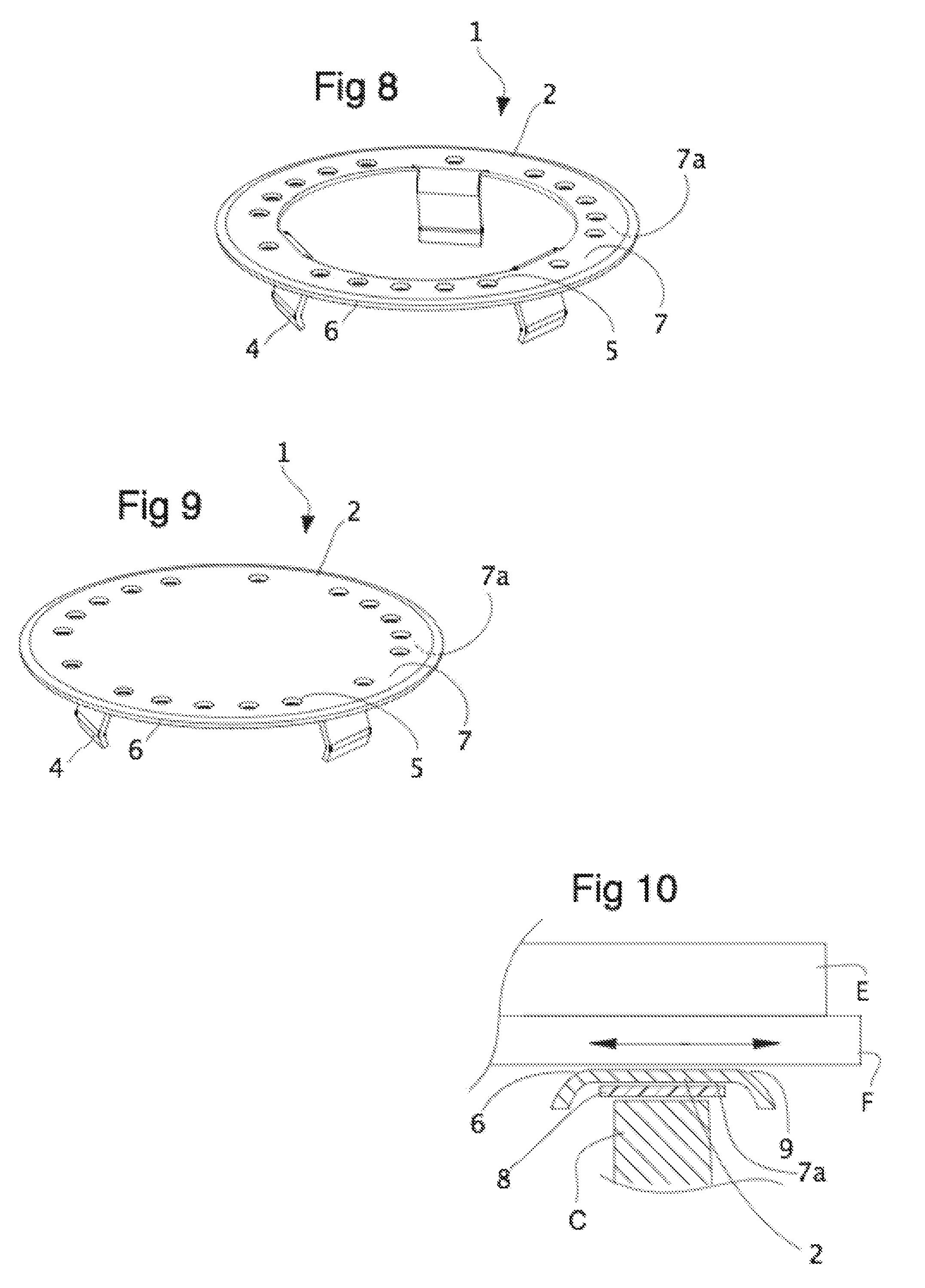
[0031]In one embodiment, the instant shim is a single disc of thin spring steel with two faces. One face is substantially flat and defines the outer working surface (i.e. the brake plate facing surface). The other face is the inner working surface (i.e. the piston facing surface). It preferably has an outer curved lip or rim, or a raised and radiused flange. The resulting shim loosely caps or partially covers the hollow piston's edge rim to provide smooth moving contact between the piston and the back plate. Piston engaging clips or tongues depend from the inner working surface to frictionally engage the inner wall of the hollow piston for shim retention.

[0032]This lip or rim allows the outer working (brake plate facing) surface to skate or slide smoothly against the plate with no corners or edges that would scrape, dig in, or cause fretting action and thereby increase friction, vibration and noise. The inner working surface (which may be cup-shaped) has sufficient clearance for the...


PUM


Abstract

The present invention is a shim or shim assembly that clips onto a brake caliper piston. It is generally a rimmed round (disc or annular) shape to cap the edges of the caliper piston and includes surface features for lubrication, and improved fitting. Reduced noise from frictional fretting is provided along with protection of piston's outer rim. Reduced thermal transfer into the piston is also provided.

Description

CROSS-REFERENCE TO RELATED APPLICATIONS[0001]This application claims benefit of Canadian patent application number 2,645,460, filed Nov. 28, 2008, which is herein incorporated by reference.BACKGROUND OF THE INVENTION[0002]1. Field of the Invention[0003]The invention relates to noise-reducing shims for disc brake systems, and more particularly relates to shims for mounting on the brake piston.[0004]2. Description of the Related Art[0005]In a disc brake caliper, a hydraulically actuated piston forces, by action and reaction, a pair of opposing brake pads to pinch a rotor attached to a vehicle wheel. Brake pads have a stiff backing plate with friction pads affixed to one side. Shims of a thin material are often used on the side of the plate contacted by the piston. The shim's function is to reduce the frequency of occurrence of a loud and annoying squeal noise from what are otherwise mechanically perfect brakes. At least some of the noise comes from the fact that, to prevent jamming, t...

Claims


Application Information

Patent Timeline
03 Jun 2010
Publication
US20100133050A1
IPC
F16D65/38
CPC
F16D65/0006; F16D2065/785; F16D65/0971
Inventors
ARBESMAN, RAY; PHAM, NGHI