Electronic device with magnetic supporting structure

a technology of supporting structure and electronic device, which is applied in the direction of stand/trestle, picture frame, kitchen equipment, etc., can solve the problems of user prompted about improper operation, additional cost due to repair and replacement, etc., to facilitate user use, improve support stability, and increase the effect of cos

Inactive Publication Date: 2010-06-03
ASUSTEK COMPUTER INC
View PDF22 Cites 104 Cited by
  • Summary
  • Abstract
  • Description
  • Claims
  • Application Information

AI Technical Summary

Benefits of technology

[0008]On the other hand, when the supporter is at the supporting position, the height of the position of the back of the electronic device body at which the magnetic element is attached is changed via the magnetic element, and thus a supporting angle can be adjusted to provide more diverse chooses to the user. At the same time, the slideway may be designed for the magnetic element to slide in, or connecting blocks may be utilized as the linkage to further provide position at different support angles to facilitate use of the user. Additionally, the supporter may be designed to include a cross-rod and a connection portion extended from two ends of the cross-rod to provide larger support area and improve support stability.
[0009]Consequently, a magnetic attraction between the magnetic supporting structure and the electronic device body can be adjusted and controlled via the magnetic element. Thus, when the user improperly operates the electronic device, applies overlarge force or knocks against the electronic device carelessly, or the electronic device is pressed by a fallen heavy object, which causes that the electronic device body is overloaded, the supporting supporter are not damaged. Furthermore, the user is prompted about improper operations, and additional cost due to repair and replacement after the supporting supporter is damaged is also avoided.

Problems solved by technology

Furthermore, the user is prompted about improper operations, and additional cost due to repair and replacement after the supporting supporter is damaged is also avoided.

Method used


Image

  • Electronic device with magnetic supporting structure
  • Electronic device with magnetic supporting structure
  • Electronic device with magnetic supporting structure

Examples


first embodiment

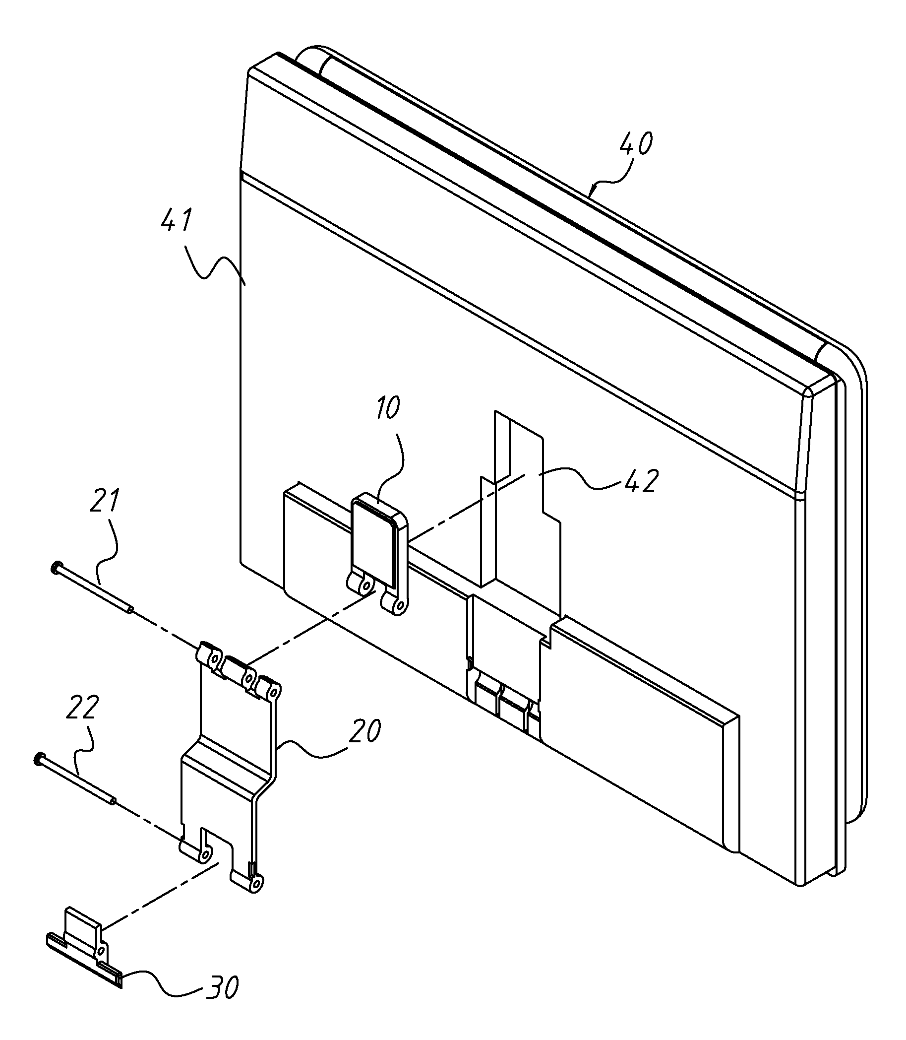
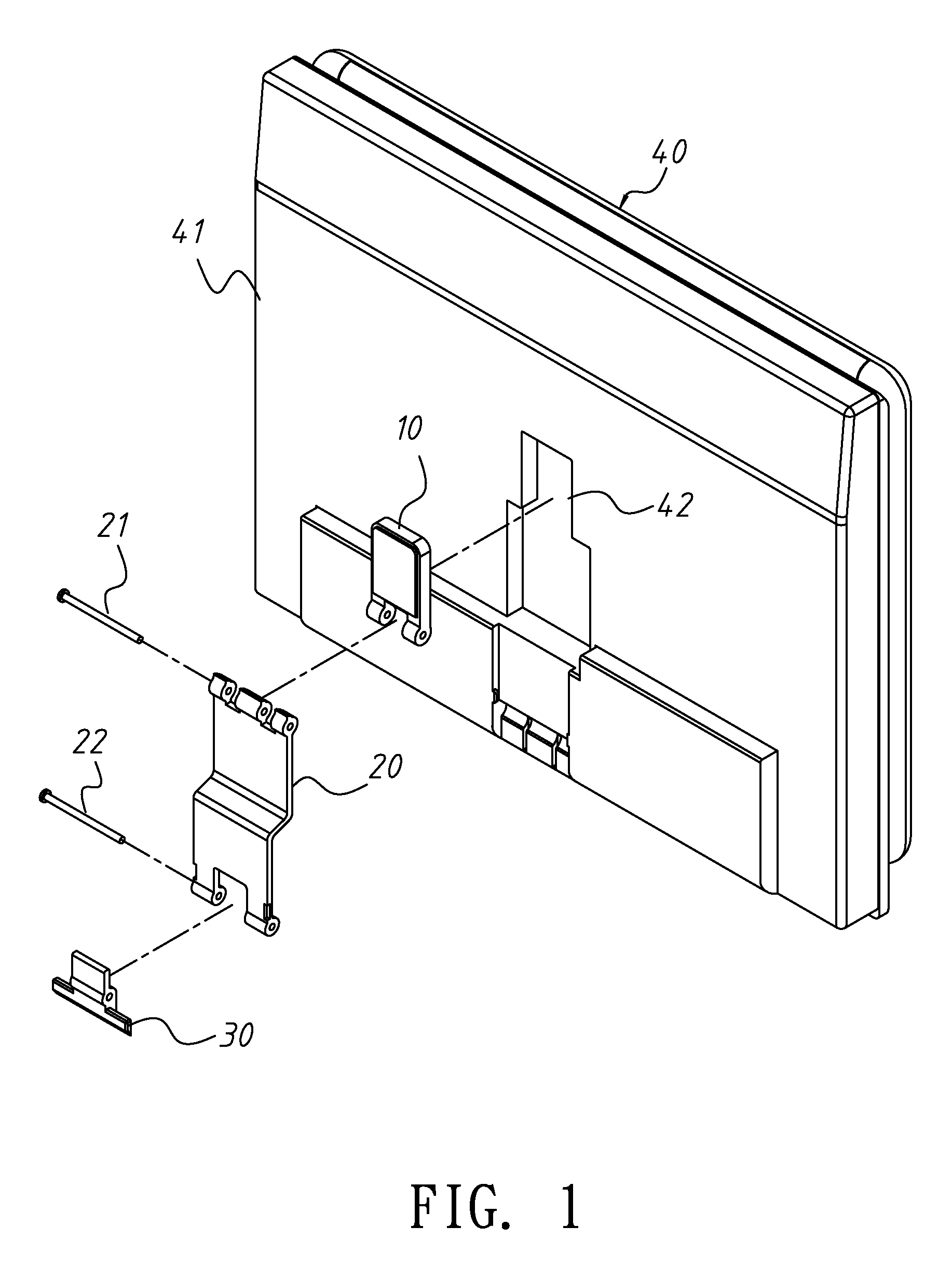
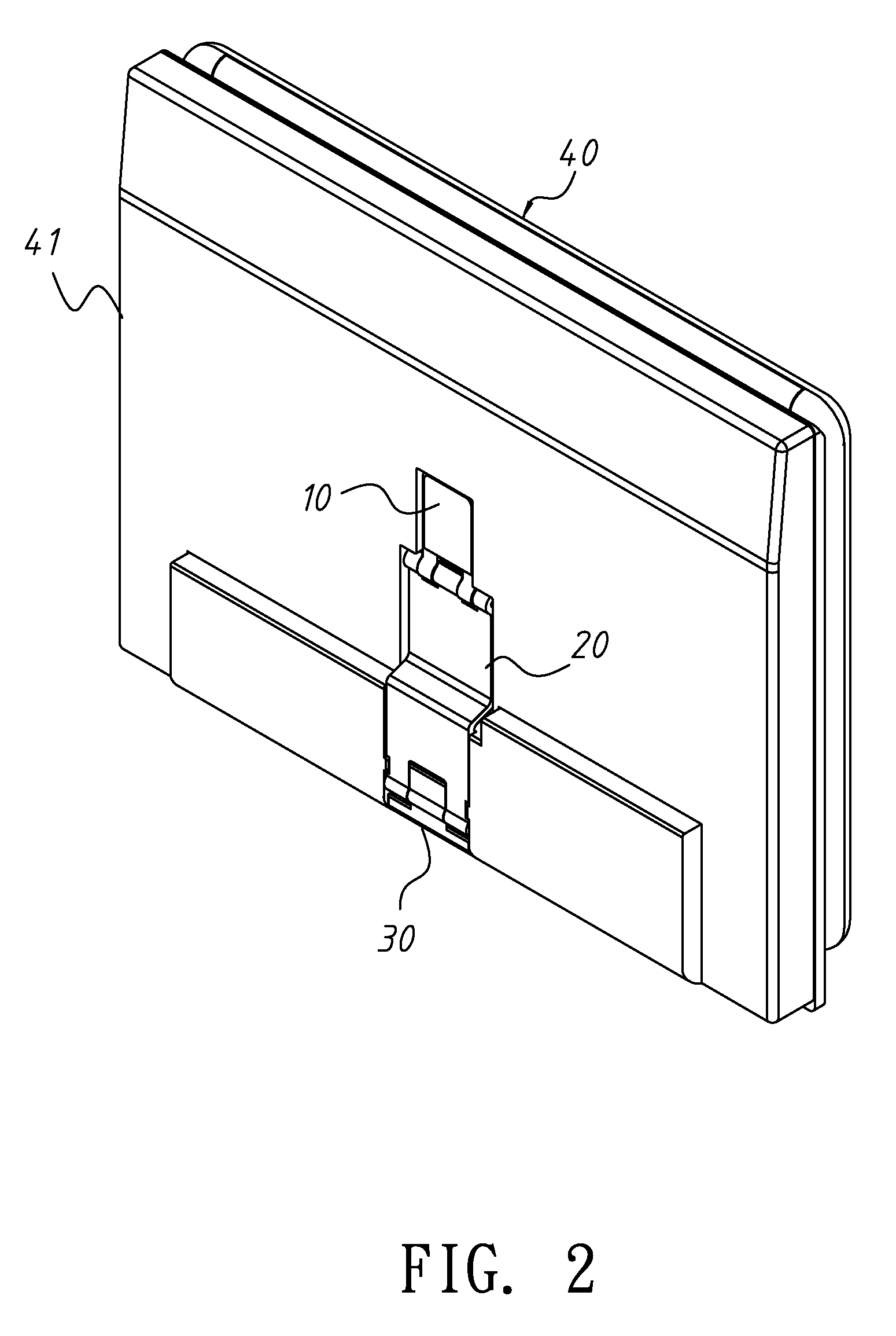
[0019]FIG. 1 is an exploded diagram showing an electronic device with a magnetic supporting structure according to the invention. FIG. 2 is an assembly diagram showing the electronic device with the magnetic supporting structure in FIG. 1.

[0020]The electronic device with the magnetic supporting structure according to the first embodiment of the invention includes an electronic device body 40 and a magnetic supporting structure. The magnetic supporting structure includes a magnetic element 10, a linkage 20, and a supporter 30. The magnetic supporting structure can be disposed at a back 41 of the electronic device body 40 to support the electronic device body 40 at a certain angle. Thus, a user may operate the electronic device more easily. The magnetic element 10 may be a magnet, a combination member with metal covering a magnetic object, and the magnetic element 10 is attached to the back 41 of the electronic device body 40 via its magnetism.

[0021]A containing space 42 is formed at ...

second embodiment

[0031]On the other hand, to improve the support ability of the supporter, FIG. 5 is an exploded diagram showing an electronic device with a magnetic supporting structure according to the invention.

[0032]The supporter 30 includes a cross-rod 31. The width of the cross-rod 31 is equal to that of the electronic device body 40. Connection portions 32 and 33 are extended from two ends of cross-rod 31, respectively. The cross-rod 31 is pivotally connected with two ends of the bottom of the back 41 of the electronic device body 40 via the connection portions 32 and 33, respectively. At the same time, the magnetic element 10 is shaped like a sliding block, and cooperating with a slideway 43 at the back 41 of the electronic device body 40, the magnetic element 10 can slide in the slideway 43. Similarly, if the outer housing of the electronic device body 40 is made of the nonmagnetic material such as the reinforced plastic, the magnetic metal needs to be laid in the slideway 43. The linkage 2...

third embodiment

[0036]FIG. 7A˜7B are exploded diagrams showing an electronic device with a magnetic supporting structure according to the invention.

[0037]The linkage 20 includes a first sliding block 23 and a second sliding block 24. The first sliding block 23 has two grooves 25. The second sliding block 24 is restricted to slide in the grooves 25 via fixing elements 26 to allow the first sliding block 23 to slide relative to the second sliding block 24. As shown in FIG. 7A and FIG. 7B, the fixing element 26 is a cooperation of a screw and a nut. Certainly, the fixing elements 26 may be replaced by tenons or protrudent dots.

[0038]FIG. 8A˜8B are schematic diagrams showing changes of the supporting positions of the electronic device with the magnetic supporting structure in FIG. 7A˜7B.

[0039]When the supporter 30 is at the storing position, as shown in FIG. 8A, the magnetic element 10 and the linkage 20 are kept via the containing space 42 to maintain the consistency of the appearance to make the supp...


PUM


Abstract

A linkage and a supporter are attached to a back of the housing via a magnetic element of an electronic device with a magnetic supporter. The supporter is drawn to a supporting position via the linkage to support the electronic device body and provide various angles for the user to easily operate the electronic device in several modes. Moreover, since the linkage and the supporter are attached via the magnetic element, when the electronic device body is overloaded, for example, a user applies overlarge force to operate a touch panel, the magnetic element is detached from the electronic device body to prevent the linkage and the supporter from being damaged or permanently destroyed.

Description

BACKGROUND OF THE INVENTION[0001]1. Field of Invention[0002]The invention relates to an electronic device with a magnetic supporting structure, more particularly to a magnetic supporting structure attached to the electronic device via a magnetic element.[0003]2. Related Art[0004]To cooperate with operation habits of users, a supporter may be disposed at an electronic device such as a notebook or a tablet computer to support the electronic device at various angles. Thus, a user may operate the electronic device easily. Common operation angles may be divided into high angles (about 70˜80 degrees), middle angles (about 40˜60 degrees), and low angles (about 20˜35 degrees). At the high angles, the electronic device can be used as a digital frame or a stock machine. At the middle angles, the user can adjust the electronic device to a proper angle when he makes a report with a projected image to easily remind the user of contents of the report or touch the electronic device to control it a...

Claims


Application Information

Patent Timeline
Patent Type & Authority Applications(United States)
IPC IPC(8): A47B96/06
CPCA47B23/043
Inventor CHIU, HSIEN-CHENGCHEN, CHENG-HONGYANG, MENG-JULIAO, CHIH-CHENG
Owner ASUSTEK COMPUTER INC
Why Eureka
Try Eureka