Area light source apparatus and liquid crystal display apparatus assembly

a technology of liquid crystal display and light source apparatus, which is applied in the direction of display means, instruments, semiconductor devices, etc., can solve the problems of color unevenness or luminance unevenness in the space, and color unevenness or luminance unevenness is likely to stand out, so as to improve performance, reduce power consumption, and increase contrast

Inactive Publication Date: 2010-06-03
SONY CORP
View PDF4 Cites 4 Cited by
  • Summary
  • Abstract
  • Description
  • Claims
  • Application Information

AI Technical Summary

Benefits of technology

[0038]Thus, in the present invention, in the proximity of each light emitting assembly, dummy lenses same as a lens which forms the light emitting element assembly are disposed. Accordingly, such a situation that, when light emitted from a certain light emitting element assembly enters a lens which composes another light emitting element assembly and then emerges from the lens, radiation of the light emitted from the certain light emitting element assembly becomes asymmetrical with respect to an axis of the light emitting element assembly can be prevented. As a result, occurrence of such a problem that, in a space positioned above the light emitting diode assembly group, a region within which the mixture state of red light, green light and blue light is non-uniform increases can be suppressed with certainty.
[0039]Further, where the partial driving method (divisional driving method) is adopted in the present invention, since the luminance distribution when one of the display area units is energized to emit light is uniformized, design for improvement in performance (increase in contrast, reduction in power consumption and so forth) is facilitated. Furthermore, also the luminance distribution when a plurality of display area units are energized to emit light at the same time is uniformized.
[0040]Further, in the present invention, if the partial driving method (divisional driving method) is adopted and the luminance of a light source which composes an area light source unit corresponding to each display area unit is controlled by the driving circuit so that the luminance of a pixel when it is assumed that a control signal corresponding to an input signal having a value equal to the display area unit input signal maximum value xU-max is supplied to the pixel may be obtained, that is, the display second prescribed value y2 at the light transmittance first prescribe value Lt1 may be obtained, then reduction of the power consumption of the area light source apparatus can be achieved. Besides, increase of the white level and reduction of the black level can be achieved. Consequently, a high contrast ratio which is a ratio in luminance between a full black display portion and a full white display portion which do not include external light reflection and so forth on the screen surface of the liquid crystal display apparatus can be achieved, and the brightness of a desired display area can be emphasized. Therefore, improvement in the quality of image display can be anticipated.

Problems solved by technology

As a result, in a space above the light emitting diode assembly groups, a region within which the mixture state of the red light, green light and blue light is non-uniform increases, which gives rise to a problem that color unevenness or luminance unevenness occurs in the space.
Particularly where one area light source unit is energized to emit light in an area light source apparatus of the partial driving type, since the influence from the other area light source units disappears, color unevenness or luminance unevenness is likely to stand out.

Method used


Image

  • Area light source apparatus and liquid crystal display apparatus assembly
  • Area light source apparatus and liquid crystal display apparatus assembly
  • Area light source apparatus and liquid crystal display apparatus assembly

Examples


embodiment 1

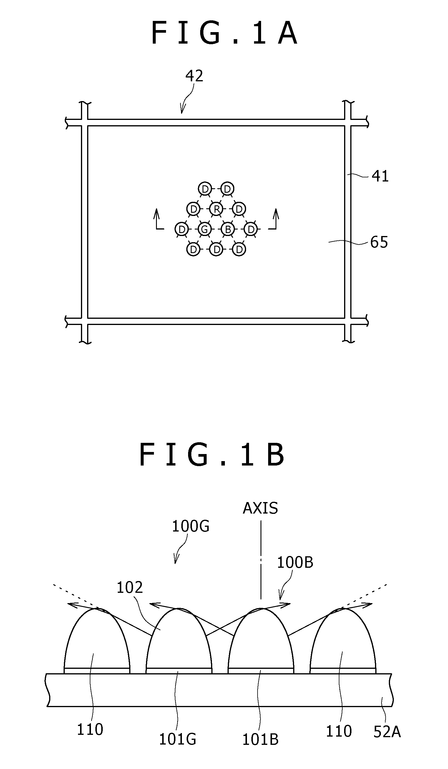
[0071]The Embodiment 1 according to the present invention relates to an area light source apparatus and a liquid crystal display apparatus assembly. FIG. 1a shows an area light source unit 42 of the area light source apparatus 40 according to the Embodiment 1 as viewed from above, and FIG. 1B shows the area light source unit 42 as viewed from sidewardly as viewed in the direction indicated by an arrow mark in FIG. 1A.

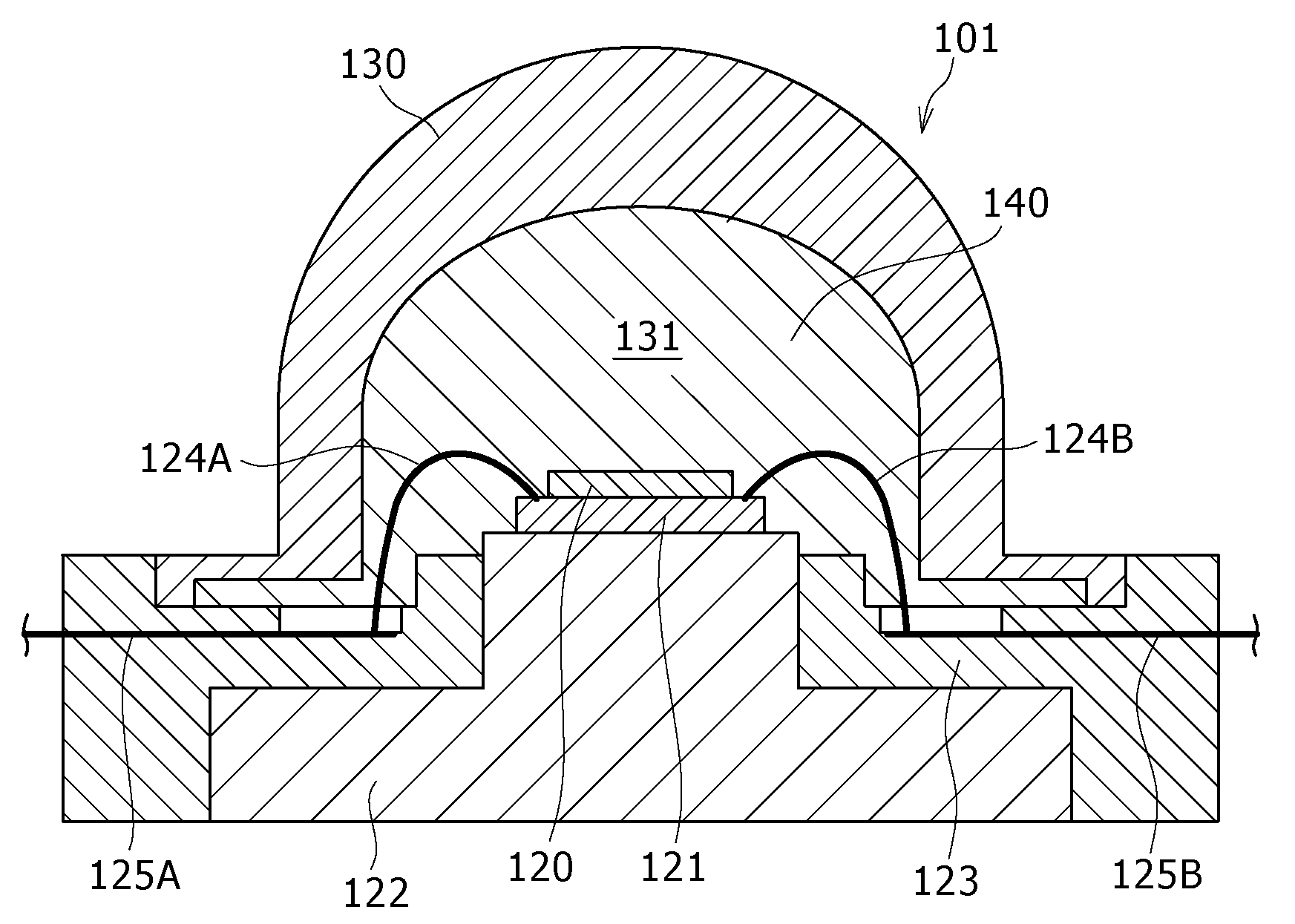
[0072]The area light source apparatus 40 includes P×Q area light source units 42 as described hereinabove. Each of the area light source units 42 includes a plurality of light emitting element assemblies 100R, 100G, 100B each including a light emitting element (light emitting diode 101) and a lens 102 through which light emitted from the light emitting element (light emitting element 101) passes and serving as a light source. The light emitting element assemblies 100R, 100G, 100B are secured to the bottom face 52A of the housing 51 by a suitable method. Further, the len...

embodiment 2

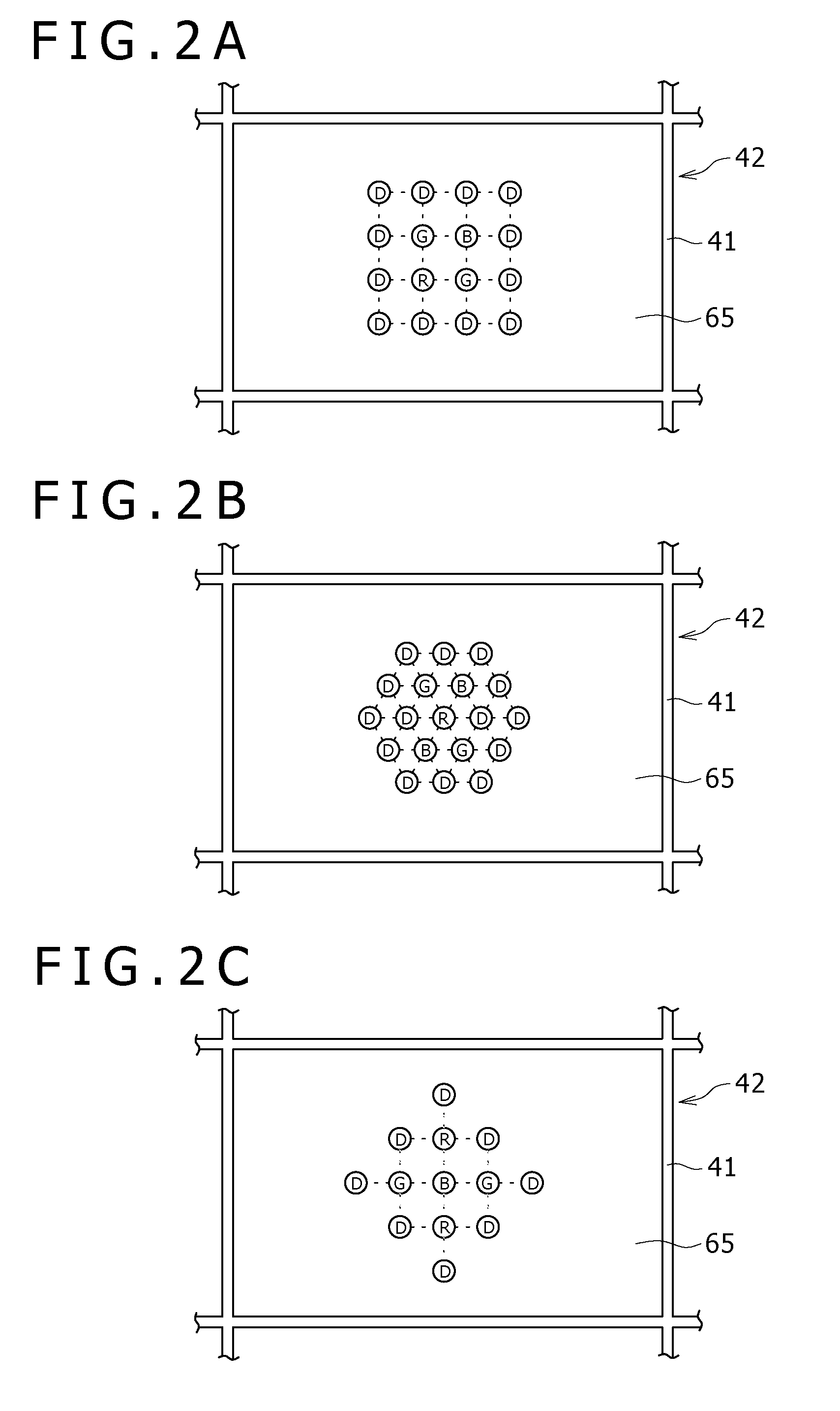
[0078]The Embodiment 2 is a modification to the Embodiment 1. The area light source unit 42 of the area light source apparatus 40 according to the Embodiment 2 may have such top plan arrangements as seen in FIGS. 2A, 2B and 2C. In the arrangement shown in FIG. 2A, one light emitting element assembly group is formed from a plurality of light emitting element assemblies, particularly one red light emitting element assembly 100R, two green light emitting element assemblies 100G and one blue light emitting element assembly 100B, positioned at the vertices of one imaginary square (indicated by broken lines). Further, a plurality of dummy lenses, particularly 12 dummy lenses 110, are disposed on the outer side of the light emitting element assembly group such that they are positioned at the vertices of imaginary squares of a shape same as that of the imagery square. Meanwhile, in the arrangement shown in FIG. 2B, one light emitting element assembly group is formed from a plurality of ligh...


PUM


Abstract

Disclosed herein is an area light source apparatus for illuminating a liquid crystal display apparatus of the transmission type, which has a display area formed from a plurality of pixels arrayed in a two-dimensional matrix, from the back, including: a plurality of light emitting element assemblies each provided as a light source and each including a light emitting element and a lens through which light emitted from the light emitting element passes; and a plurality of dummy lenses disposed in the proximity of each of the light emitting element assemblies and configured same as the lenses of the light emitting element assemblies.

Description

RELATED APPLICATION DATA[0001]This application is a division of U.S. patent application Ser. No. 11 / 936,420, filed Nov. 7, 2007, the entirety of which is incorporated herein by reference to the extent permitted by law. The present application claims the benefit of priority to Japanese Patent Application No. JP 2006-303788 filed with the Japan Patent Office on Nov. 9, 2006, the entirety of which is incorporated by reference herein to the extent permitted by law.BACKGROUND OF THE INVENTION[0002]1. Field of the Invention[0003]This invention relates to an area light source apparatus called backlight which illuminates a liquid crystal display apparatus of the transmission type, which has a display area formed from pixels disposed in a two-dimensional matrix, from the back and a liquid crystal display apparatus assembly which incorporates the area light source apparatus.[0004]2. Description of the Related Art[0005]The liquid crystal material itself in a liquid crystal display apparatus do...

Claims


Application Information

Patent Timeline
Patent Type & Authority Applications(United States)
IPC IPC(8): H01L33/00H01L33/58
CPCG02F1/133603G02F1/133609G02F1/133611H01L33/56H01L33/58H01L2224/48091H01L2224/45144H01L2924/13091H01L2924/00014H01L2924/00
Inventor MORIMOTO, TADASHI
Owner SONY CORP
Why Eureka
Try Eureka