Electric component with winding and tapping

a technology of winding and tapping, applied in the direction of magnets, manufacturing tools, magnetic bodies, etc., can solve the problems of high production costs and achieve the effect of a better winding tapping mechanism

Inactive Publication Date: 2010-06-03
ABB TECH AG
View PDF9 Cites 2 Cited by
  • Summary
  • Abstract
  • Description
  • Claims
  • Application Information

AI Technical Summary

Benefits of technology

[0008]An aspect of the present invention is therefore to provide a better mechanism for the tapping of windings of electrical components, by means of which the winding process can be improved.
[0016]According to one preferred embodiment of the invention, the winding of the electrical component according to the invention comprises at least one supporting element, which supports the conductor within the contact section. The conductor is guided in the form of a loop by the supporting element within the contact section, for example in a U shape, with the loop projecting radially with respect to an axis of symmetry of the winding. Alternatively, the supporting element may also be provided parallel to an axis of symmetry of the winding, such that, in the contact section, the conductor runs at right angles to the circumferential direction and parallel to a longitudinal axis of the winding, and partially projects from a head surface or bottom surface of the winding. The use of the supporting element improves the mechanical robustness within the contact section. Furthermore, the supporting element can be used for shaping of the conductor profile within the contact section during the course of the winding process.
[0027]In a further embodiment of the method, for production of a winding which is bounded in the axial direction, the tap is provided in that the conductor is passed out parallel to the rotation axis and inclined with respect to the local circumferential direction via a point which marks the boundary of the winding in the axial direction. A boundary such as this is, for example, marked by a head end, a head surface or a bottom surface of the winding. This allows contact to be made with the tap without having to change the completely wound winding.

Problems solved by technology

This discontinuous process leads to relatively long pauses during the winding process, and thus to ineffective utilization of the winding machines, thus incurring high production costs.

Method used


Image

  • Electric component with winding and tapping
  • Electric component with winding and tapping
  • Electric component with winding and tapping

Examples


Embodiment Construction

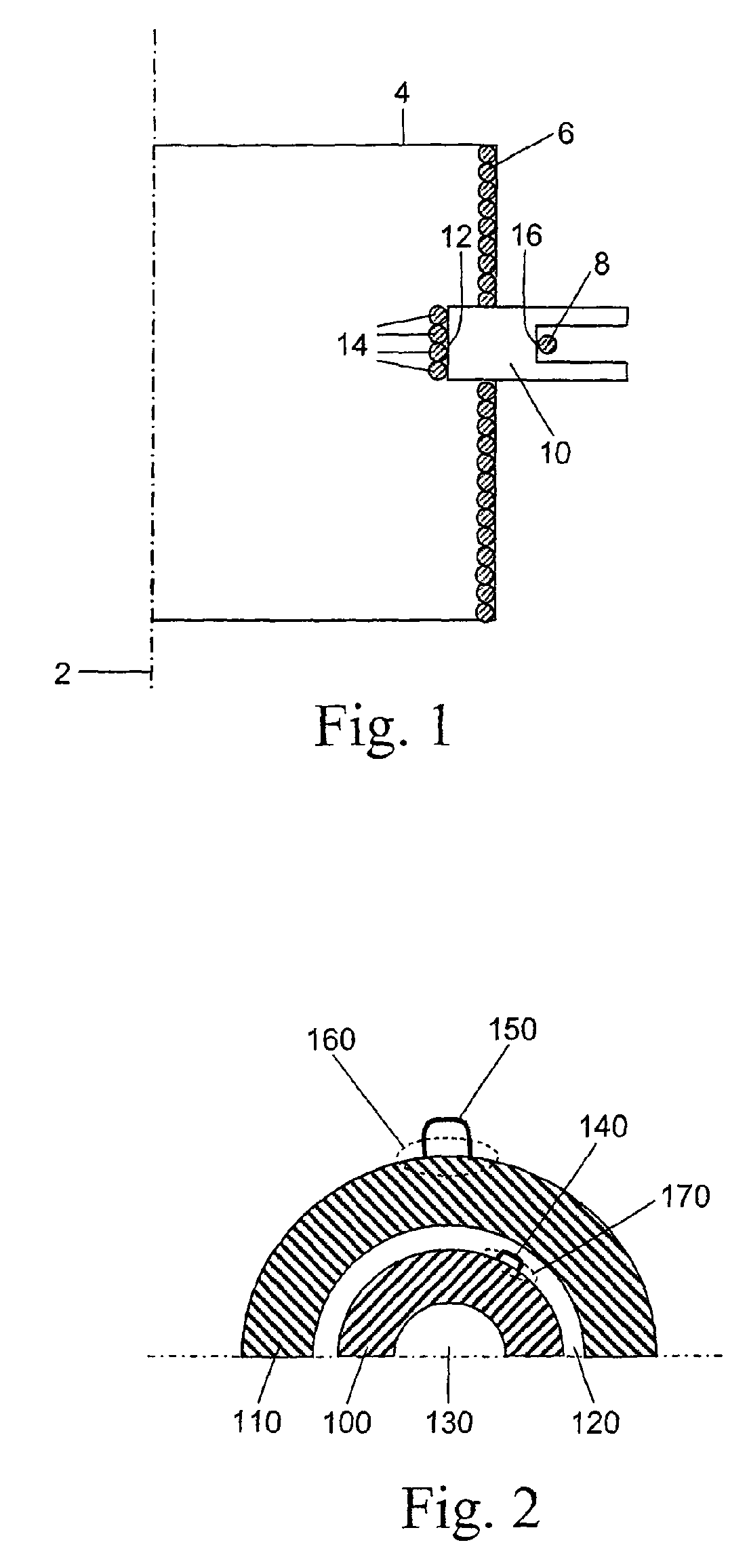
[0046]FIG. 1 shows a section view through an electrical component according to the invention on a section plane on which the longitudinal axis 2 of the electrical component is located. The external outline 4 of the winding is rectangular. As used herein, rectangular means essentially rectangular. The winding is formed from individual conductors 6, only some of which are illustrated which abut or are closest to the circumferential outer surface of the winding. FIG. 1 therefore shows a longitudinal section through a winding in the form of a column, for example a cylindrical or cuboid winding. A possible cavity in the interior of the winding, through which the longitudinal axis of the winding runs, is not illustrated.

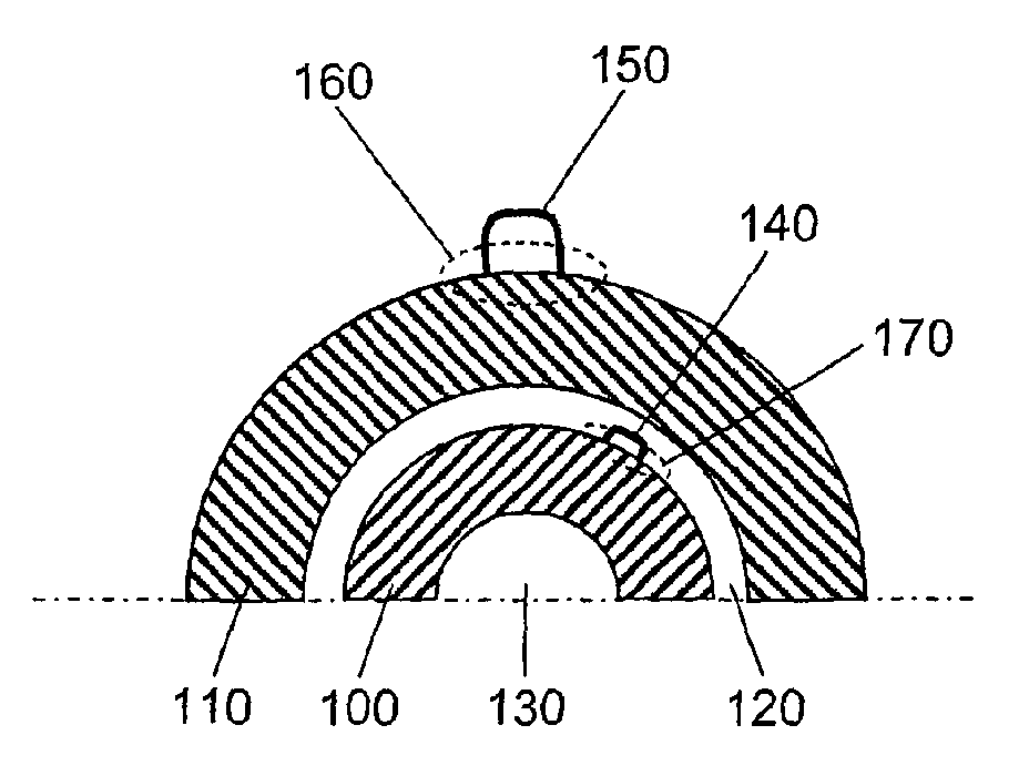
[0047]The tap 8 is formed by a supporting element 10, which is formed from an insulator, for example plastic or ceramic. This supporting element is not completely circumferential but is provided only in a contact section and therefore covers only a small angle or a small p...


PUM

PropertyMeasurementUnit
operating voltageaaaaaaaaaa

Abstract

A power transformer includes at least one winding formed from at least one conductor extending along a circumferential direction, wherein the at least one winding has a tap in a contact section formed by a profile of the at least one conductor in at least one direction inclined relative to the circumferential direction; and at least one supporting element configured to support the conductor in the contact section.

Description

[0001]This is a U.S. National Phase Application under 35 U.S.C. §171 of International Application No. PCT / EP2008 / 002873, filed on Apr. 11, 2008, which claims priority to German Patent Application No. DE 10 2007 017 702.1, filed on Apr. 14, 2007, both incorporated by reference herein. The International Application was published in German on Oct. 23, 2008 as WO 2008 / 125288 under PCT Article 21 (2).[0002]The invention relates to the provision of a tap in a winding of an electrical component. In particular, the invention relates to electrical high-power transformers or inductors with a better tapping structure.BACKGROUND[0003]Electrical components comprise windings in order to produce magnetic fields, or in order to convert electromagnetic fields to power. The main fields of use of a component such as this with windings are transformers which allow voltage and current conversions, by means of primary and secondary windings. Furthermore, windings are used in inductors in order to influen...

Claims


Application Information

Patent Timeline
Patent Type & Authority Applications(United States)
IPC IPC(8): H01F27/29H01F41/06H01F41/10
CPCH01F27/29H01F41/0666Y10T29/4902Y10T29/5313Y10T29/53209H01F41/076
Inventor ZILLMANN, KARLKREFELD, DIETMAR
Owner ABB TECH AG
Why Eureka
Try Eureka