Laminate Surface Covering Suited for Marine Environments

a marine environment and surface covering technology, applied in the field of surface coverings, can solve problems such as the network of voids, and achieve the effect of improving the bonding mechanism and enhancing the structural integrity of the surface covering member

Inactive Publication Date: 2017-10-12
WEISENBERG KENT
View PDF8 Cites 1 Cited by
  • Summary
  • Abstract
  • Description
  • Claims
  • Application Information

AI Technical Summary

Benefits of technology

[0008]A reinforcing mounting layer may be adhered to the closed cell polymer foam sub-layer to enhance the structural integrity of the surface covering member, such as for example a fiber reinforced or woven sheet member in the form of a fabric, woven fiberglass, mesh or felt, and to provide a better bonding mechanism for affixation of the surface covering member to the substrates, the mounting layer being porous to the mounting adhesive. An intermediary layer composed of a screen or mesh may be positioned between the bottom mounting layer and the foam sub-layer, the apertures of this intermediary layer being significantly greater than the apertures of the mounting layer. This intermediary layer provides receptacles to receive the bonding material, such as an epoxy, that is used to adhere the surface covering member to the substrate.
[0009]The upper bonded granular layer is formed by mixing the polymer granules and a polymeric adhesive to form a sludge, placing the sludge mixture onto a horizontal vibration bed between form members, preferably with the sub-layer already positioned within the form, screeding the mixture to get the proper height, then tamping and vibrating the mixture to properly orient and settle the particles to produce a mat of the desired thickness and density. This methodology results in an extensive network of voids and irregular channels within the upper layer, such that water and other liquids will readily move into and then laterally within the layer for rapid drainage to preclude surface pooling of the liquid. The composite laminate surface covering member so produced can be cut to any desired shape.

Problems solved by technology

This methodology results in an extensive network of voids and irregular channels within the upper layer, such that water and other liquids will readily move into and then laterally within the layer for rapid drainage to preclude surface pooling of the liquid.

Method used


Image

  • Laminate Surface Covering Suited for Marine Environments
  • Laminate Surface Covering Suited for Marine Environments

Examples


Embodiment Construction

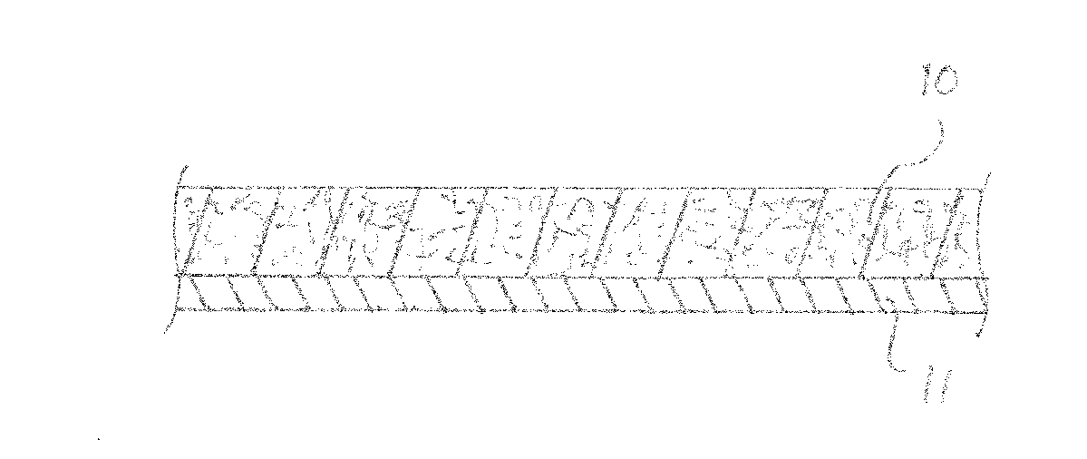
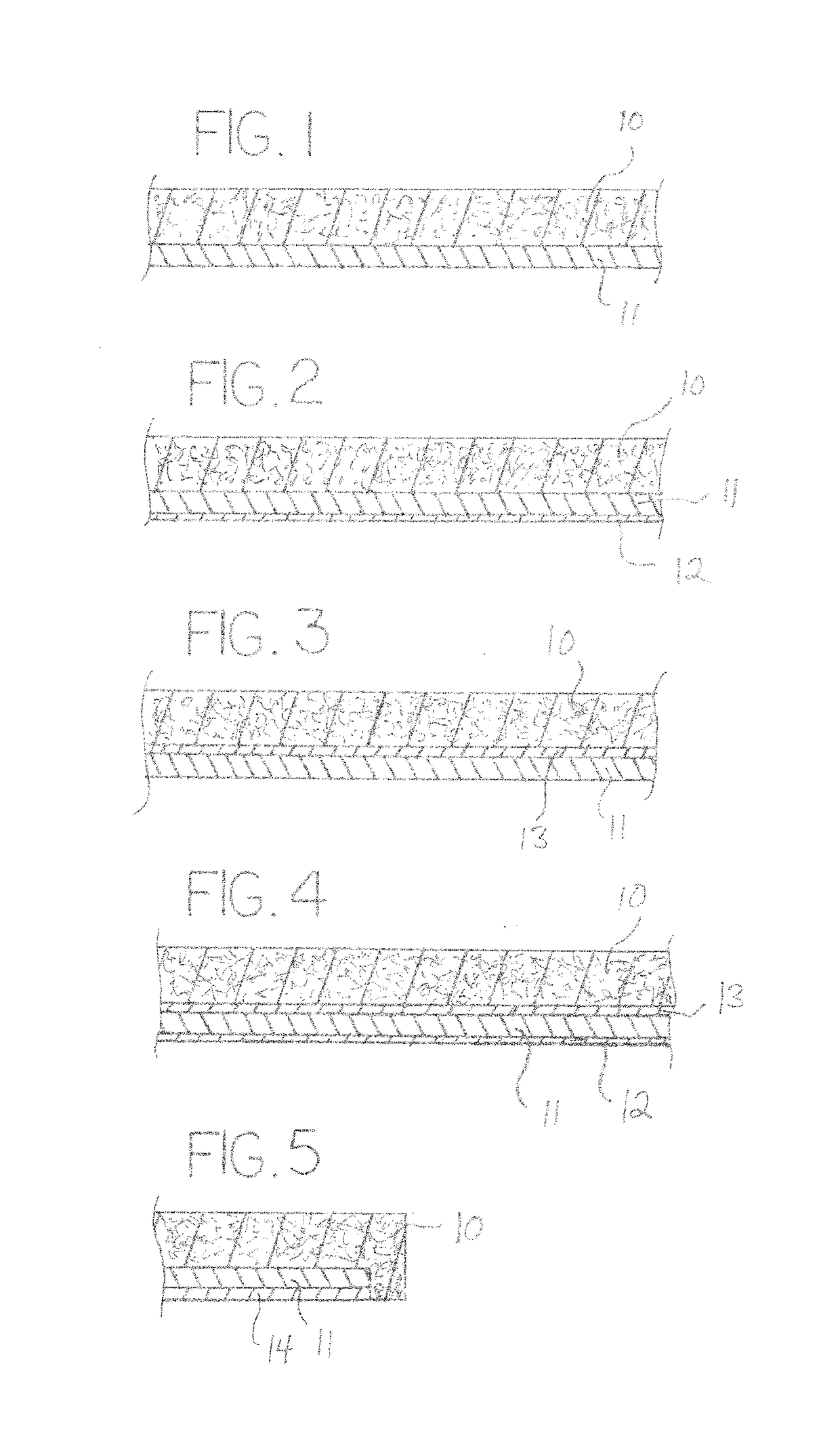
[0017]Various embodiments of the invention shall now be described in detail with reference to the drawings, the drawings presenting non-limiting illustrations of embodiments of the invention. The drawings are not to scale.

[0018]The invention is a composite laminate, i.e., multi-layer, surface covering member in the form of a sheet, panel or mat (i.e., a thin member having a thickness dimension significantly smaller than its lateral dimensions) that is adapted to be placed onto horizontal support surfaces, such as for example the deck members of a marine dock, or wrapped or otherwise applied to horizontal or vertical structural members, such as for example marine post members. The surface covering member is preferably mounted to the support surfaces and structural members with adhesives or mechanical fasteners. The term “substrates” shall be used herein to collectively refer to the support surfaces and the structural members. The surface covering is particularly structured and suitab...


PUM

PropertyMeasurementUnit
sizeaaaaaaaaaa
diameteraaaaaaaaaa
thicknessaaaaaaaaaa

Abstract

A composite laminate surface covering member in the form of a sheet, panel or mat having an upper layer of bonded, vibration oriented, polymer granules, the upper layer being water permeable and possessing an extensive irregular channeling system formed by the voids between the granules, and a sub-layer of a closed cell polymer that is water impermeable. Additional layers for reinforcing purposes may also be present.

Description

[0001]This application claims the benefit of U.S. Provisional Patent Application Ser. No. 62 / 319,551, filed Apr. 7, 2016, the disclosure of which is incorporated herein by reference.BACKGROUND OF THE INVENTION[0002]This invention relates generally to surface coverings for horizontal support surfaces, such as floors, walkways, docks, etc., and for other structural members, such as posts, railings, etc., and in particular such surfaces or members that are exposed to the environment, and even more particularly to such surfaces or members that are in outdoor marine environments.[0003]Many surfaces and structural members are exposed to the environments and thereby subjected to environmental degradation, soiling, the growth of mold or mildew, dangerous loss of traction, etc. Wooden or composite material docks extending over bodies of water and exposed to the elements are particularly susceptible to environmental degradation.[0004]Most waterfront homes and waterfront commercial venues have...

Claims


Application Information

Patent Timeline
Patent Type & Authority Applications(United States)
IPC IPC(8): B32B5/18B32B5/02B32B7/12
CPCB32B5/18B32B7/12B32B2266/02B32B2266/08B32B5/028B32B5/022B32B5/16B32B5/245B32B5/30B32B3/26B32B2250/04B32B2260/021B32B2260/046B32B2262/101B32B2262/106B32B2264/0221B32B2264/0257B32B2264/12B32B2266/0207B32B2266/025B32B2307/30B32B2307/726B32B2307/7265B32B2307/744B32B2471/00
Inventor WEISENBERG, KENT
Owner WEISENBERG KENT
Why Eureka
Try Eureka