Detecting Method for Photo-Sensor Touch Panel and Touch-Sensitive Electronic Apparatus using the same

Active Publication Date: 2010-06-03
AU OPTRONICS CORP
View PDF7 Cites 30 Cited by
  • Summary
  • Abstract
  • Description
  • Claims
  • Application Information

AI Technical Summary

Benefits of technology

[0012]In the above-mentioned embodiments of the present invention, two different threshold brightnesses are used for performing relative operations, one of the threshold brightnesses can be used for finding out a shadow area caused by a pointer shading light, and the other one of the threshold brightnesses can be used for finding out an area in the shadow area which is corresponding to light being shaded by the pointer at a particular level. Then, a relative distance between two data points located at respective corresponding positions of the two areas can be used to determine whether a real touch probably/really occurred. As long as the relative distance is smaller than a predetermined distance, it is determined that a real touch probably/really occurred according to user's definition. Once it is determined that a real touch probably occurred, the amount of data points located in the area which is corresponding to light being shaded at a particular level and having the relative distances smaller tha

Problems solved by technology

Therefore, if the foregoing method for detecting the central position of the touch area is employed, the central position of the real touch a

Method used


Image

  • Detecting Method for Photo-Sensor Touch Panel and Touch-Sensitive Electronic Apparatus using the same
  • Detecting Method for Photo-Sensor Touch Panel and Touch-Sensitive Electronic Apparatus using the same
  • Detecting Method for Photo-Sensor Touch Panel and Touch-Sensitive Electronic Apparatus using the same

Examples


Embodiment Construction

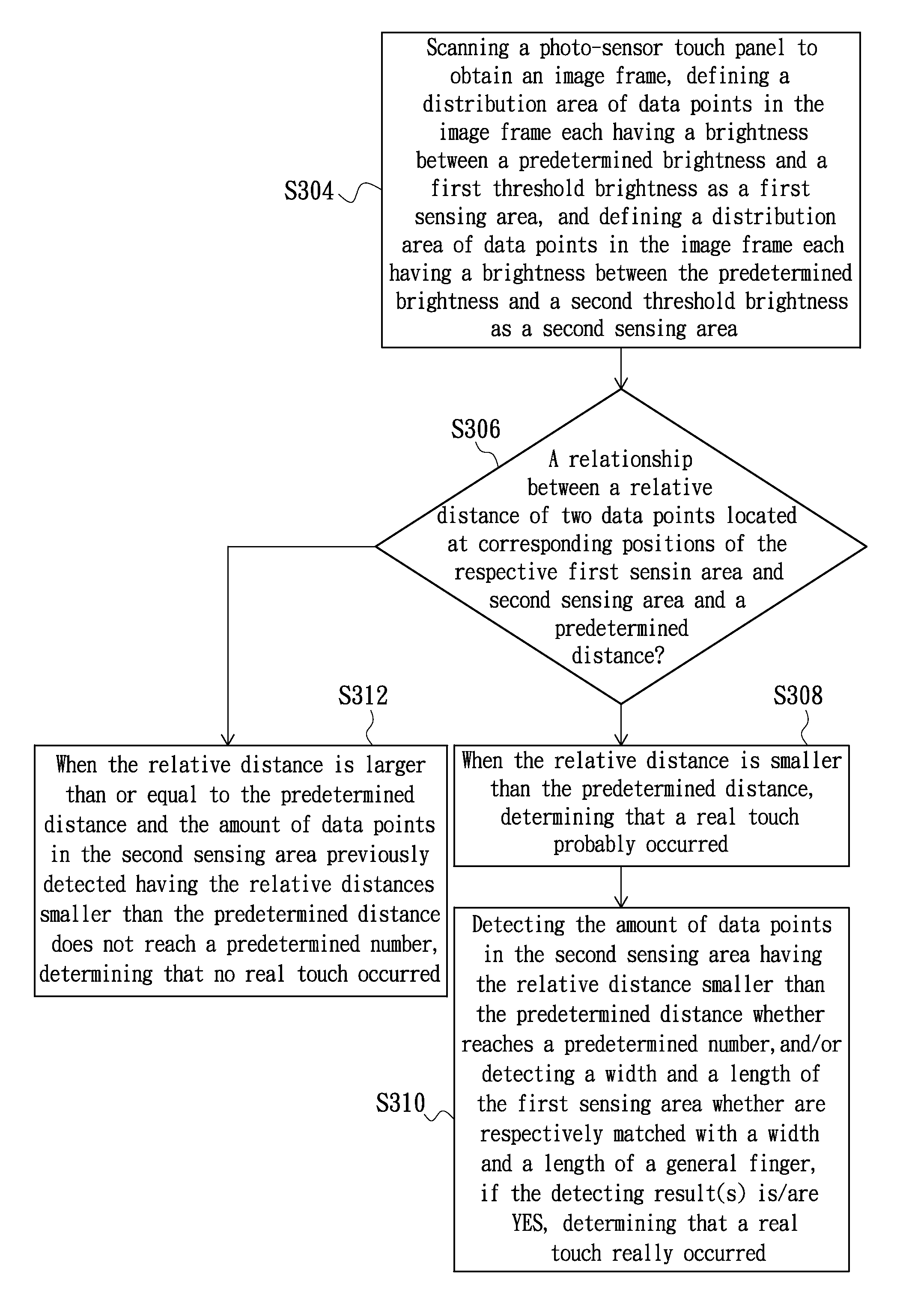
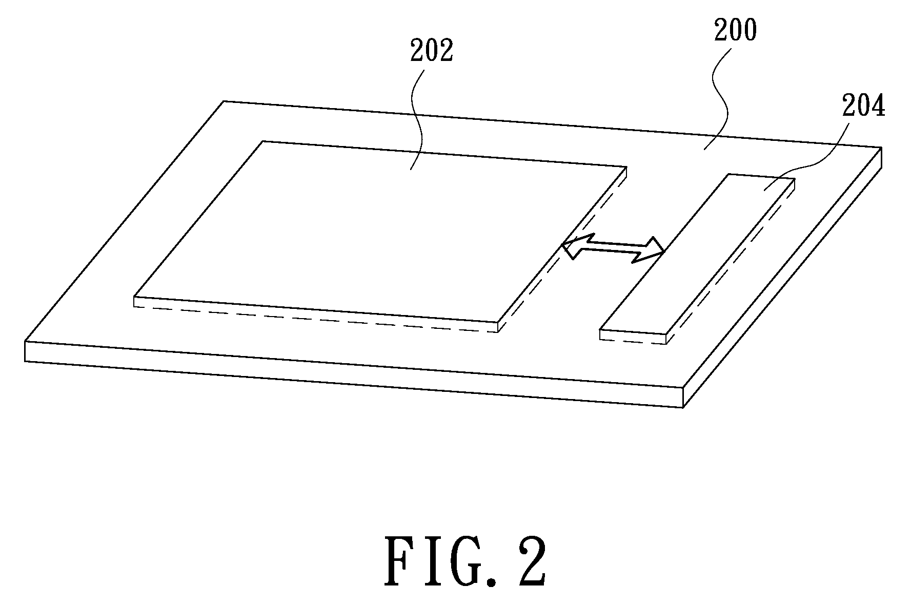
[0018]FIG. 2 illustrates a touch-sensitive electronic apparatus in accordance with an embodiment of the present invention. The touch-sensitive electronic apparatus 200 includes a photo-sensor touch panel 202 and a control circuit 204. FIG. 3 is a flowchart of a detecting method for a photo-sensor touch panel in accordance with an embodiment of the present invention. Please refer to FIG. 2 and FIG. 3 according to the need of description. The control circuit 204 is configured (i.e., structured and arranged) for scanning the photo-sensor touch panel 202 to obtain an image frame, defining a distribution area of data points in the image frame each having a brightness between a predetermined brightness and a first threshold brightness as a first sensing area, and defining a distribution area of data points in the image frame each having a brightness between the predetermined brightness and a second threshold brightness as a second sensing area (as illustrated by the step S304 of FIG. 3). ...


PUM


Abstract

An exemplary detecting method for a photo-sensor touch panel and a touch-sensitive electronic apparatus using the same are provided. In aforementioned method, an image frame is obtained by scanning the photo-sensor touch panel. Then, a distribution area of data points in the image frame each having a brightness between a predetermined brightness and a first threshold brightness is defined as a first sensing area, and a distribution area of data points in the image frame each having a brightness between the predetermined brightness and a second threshold brightness is defined as a second sensing area. Afterward, it is determined that whether a real touch probably/really occurred according to a relative distance between one of first data points and corresponding one of second data points. The first data points located in the first sensing area, and the second data points located in the second sensing area.

Description

CROSS-REFERENCE TO RELATED APPLICATIONS[0001]This application is based upon and claims the benefit of priority from the prior Taiwanese Patent Application No. 097146954, filed Dec. 3, 2008, the entire contents of which are incorporated herein by reference.BACKGROUND[0002]1. Technical Field[0003]The present invention generally relates to touch control technologies and, particularly to a detecting method for a photo-sensor touch panel and a touch-sensitive electronic apparatus using the same.[0004]2. Description of the Related Art[0005]FIG. 1 is a schematic view of illustrating a method for detecting a central position of a touch area sensed by a photo-sensor touch panel, in accordance with the prior art. As illustrated in FIG. 1, the numerical reference 100 represents an image frame obtained by scanning the photo-sensor touch panel (not shown). The image frame 100 is consisted of 256 data points (as labeled by the numerical reference 102) arranged in a matrix of 16 columns and 16 row...

Claims


Application Information

Patent Timeline
IPC IPC(8): G06F3/042
CPCG06F3/042G06F3/0418
Inventor YANG, CHUN-WEIHSU, YU-MINCHENG, YUNG-TSE
Owner AU OPTRONICS CORP
Why Eureka
Try Eureka