Laser noise detection and mitigation in particle counting instruments

a particle counting and laser noise technology, applied in the field of optical particle analyzers, can solve the problems of limiting the sensitivity and particle sizing capability, the state of the art optical particle counter is currently susceptible to problems, and the count adversely affecting the accuracy and sensitivity of the system, so as to reduce false positives and effectively distinguish signals

Active Publication Date: 2018-06-05
PARTICLE MEASURING SYST
View PDF31 Cites 16 Cited by
  • Summary
  • Abstract
  • Description
  • Claims
  • Application Information

AI Technical Summary

Benefits of technology

[0007]This invention relates to optical particle counters and methods capable of effectively distinguishing signals generated from particle light scattering from sources of noise. Embodiments of the invention, for example, use multisensory detector configurations for identifying and distinguishing signals corresponding to fluctuations in laser intensity from signals corresponding to particle light scattering for the detection and characterization of submicron particles. In an embodiment, for example, methods and systems of the invention compare signals from different detector elements of a detector array to identify and characterize noise events, such as noise generated from laser intensity instability, thereby allowing for the detection and characterization of smaller particles. The system and methods of the present invention, thus, provide an effective means of reducing false positives caused by noise or interference while allowing for very sensitive particle detection.
[0008]In some embodiments, the systems and methods of the invention achieve effective characterization of detector signals on the basis of the spatially distribution characteristics of scattered and / or emitted light, as implemented using a detector configuration comprising a plurality of detectors to independently view different portions of a viewing region. In some embodiments, the systems and methods of the invention achieve effective characterization of detector signals on the basis of temporal characteristics upon, during and / or after the detection of a laser noise event. The systems and methods provided are highly versatile and may be used for the detection and characterization of a range of particles, including particles with small physical dimensions (e.g., optionally <1 micron, optionally <0.5 microns), in a wide range of fluids, such as ultrapure water and process chemicals.

Problems solved by technology

In addition to limitations on sensitivity and particle sizing capability, state of the art optical particle counters are currently susceptible to problems relating to false counts generated when detector noise and / or signals resulting from processes other than optical scattering from particles are attributed to a particle detection event.
The occurrence of false counts adversely impacts accuracy and sensitivity of the systems.
Furthermore, the occurrence of false counts also impedes the capability of optical particle analyzers to accurately detect and characterize particles having small physical dimensions (e.g., less than 0.5 microns).

Method used


Image

  • Laser noise detection and mitigation in particle counting instruments
  • Laser noise detection and mitigation in particle counting instruments
  • Laser noise detection and mitigation in particle counting instruments

Examples


example 1

Identification and Discrimination of Laser Noise Events Using a Multi-element Detector Configuration.

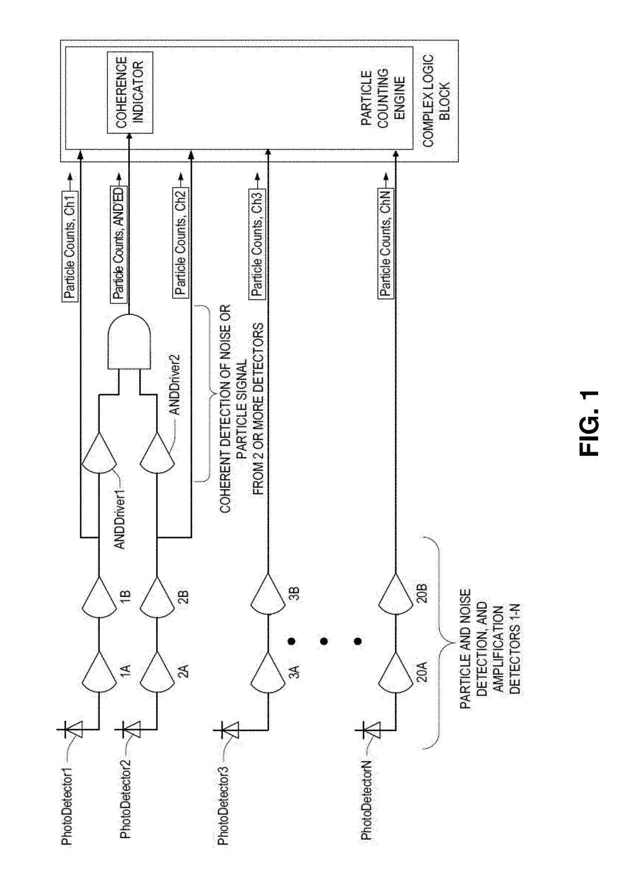
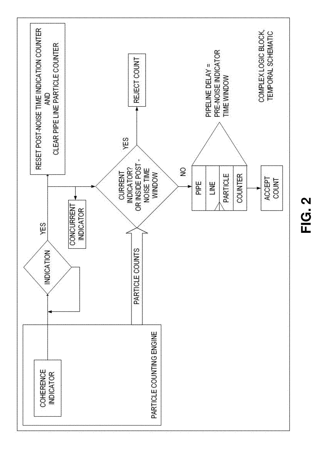
[0041]In embodiments of the present invention, when using multi-element photonic detectors for detection of submicron particles in fluids; liquid or aerosol, it is beneficial to utilize one or more of detector elements to distinguish between the very low signal level that is generated when a nano-size particle passes through the sampling region, and the increase in light level when the light source undergoes brief periods of positive light intensity fluctuations. In light scattering particle counters, as a particle passes thru the sampling region it generates an increase in light scattered signal above the background molecular scatter of the sample fluid. When the light source, which is typically a laser in state of the art particle counters, experiences a momentary unstable state, its light output can “burst” in output intensity. These bursts periods are typically referred to as las...

example 2

Experimental Performance Evaluation

[0050]Laser light noise variation in available state-of-the-art diode-pumped solid-state (DPSS) lasers becomes a greater proportion of the SNR (Signal to Noise Ratio) in light scattering based Particle Counters as the push for detection of smaller and smaller particles in the fluid samples continue. As described above, changes in temperature of a laser cause a laser's cavity length to change, which in turn causes mode-hopping and unstable noise bursting in the laser's light intensity. In the following tests, laser noise was approximated by intentionally changing the temperature of the laser. To produce a changing temperature surrounding the instrument and its laser, a temperature controlled cabinet that uses a TEC (Thermal Electric Cooler) was used. The specific use of a cabinet that utilizes a TEC was important because unlike temperature controlled chambers that use refrigeration, the TEC does not generate Line Conducted electrical noise that migh...

example 3

Array Detector Embodiments for Laser Noise Detection and Mitigation

[0082]A range of array detector geometries and related signal processing methods are useful in the present methods and systems.

Detector Spacing

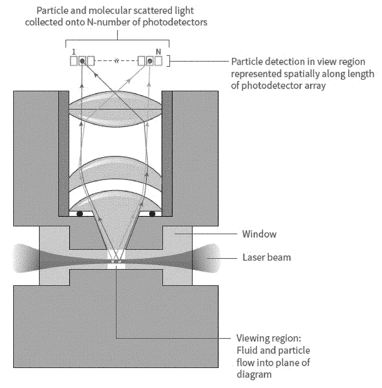
[0083]In methods and systems of embodiments of the present design, multiple detector elements are used to detect individual real particles as these particles pass through spatially separated viewing regions being witnessed by each of the separate elements.

[0084]For very small of particle sizes; e.g., having cross sectional dimensions of approximately 20 nm, the collected partial scattering of light from these particles and the amount of photon energy in each of these scattering events is enough to generate sufficient photon-generated current above the molecular background scattering and be recorded as a particle event when a high percentage of the imaged spot falls inside a single element without some of the photon energy falling into a separating region between elements, or w...


PUM

PropertyMeasurementUnit
distanceaaaaaaaaaa
time periodaaaaaaaaaa
distanceaaaaaaaaaa

Abstract

This invention relates to optical particle counters and methods capable of effectively distinguishing signals generated from particle light scattering from sources of noise. Embodiments of the invention, for example, use multisensory detector configurations for identifying and distinguishing signals corresponding to fluctuations in laser intensity from signals corresponding to particle light scattering for the detection and characterization of submicron particles. In an embodiment, for example, methods and systems of the invention compare signals from different detector elements of a detector array to identify and characterize noise events, such as noise generated from laser intensity instability, thereby allow for the detection and characterization of smaller particles. The system and methods of the present invention, thus, provide an effective means of reducing false positives caused by noise or interference while allowing for very sensitive particle detection.

Description

CROSS-REFERENCE TO RELATED APPLICATIONS[0001]This application claims the benefit of and priority to U.S. Provisional Application No. 62 / 142,141, filed Apr. 2, 2015, and U.S. Provisional Application No. 62 / 205,239, filed Aug. 14, 2015, both of which are hereby incorporated by reference in their entirety to the extent non inconsistent with the disclosure herein.BACKGROUND OF INVENTION[0002]This invention is in the field of optical particle analyzers. In an embodiment, his invention relates generally to two-dimensional optical imaging-based methods and systems for detecting and characterizing particles in fluid samples. In an embodiment, this invention also relates generally to methods and systems for improving the sensitivity and versatility of optical particle analyzers and for extending device performance of these systems so as to accurately detect and characterize particles having small physical dimensions (e.g., less than 0.1 microns).[0003]A large portion of the micro-contaminati...

Claims


Application Information

Patent Timeline
Patent Type & Authority Patents(United States)
IPC IPC(8): G01N21/00G01N21/53G01N15/14G01N15/10G01N15/00
CPCG01N21/53G01N15/1429G01N15/1459G01N2015/1488G01N2015/0053G01N2015/1006G01N2015/0038G01N21/4785G01N2015/0693G01N2015/1486G01N2201/1247G01N15/1434G01N21/94
Inventor LUMPKIN, JAMESMELTON, MATTHEW
Owner PARTICLE MEASURING SYST
Why Eureka
Try Eureka