Electrical Interconnection System

a technology of electrical interconnection and connector, which is applied in the direction of coupling contact member, connection to the device, material of the connection contact member, etc., can solve the problems of large size of connector implementation, cumbersome work, etc., and achieve the effect of thin profile, cumbersome work, and large siz

Inactive Publication Date: 2010-06-03
RAYTHEON CO
View PDF17 Cites 20 Cited by
  • Summary
  • Abstract
  • Description
  • Claims
  • Application Information

AI Technical Summary

Benefits of technology

[0005]Some embodiments of the disclosure may provide numerous technical advantages. For example, one embodiment of the electrical interconnection system may provide denser packaging of electrical systems comprising multiple subsystems. Known interconnection systems use separate connectors for electrically coupling subsystems together. Known implementations of connectors, however, are relatively large in size and may be cumbersome to work with when physically coupled to flex circuits that are have a relatively thin profile. The electrical interconnection system according to the teachings of the present disclosure is such that subsystems may be interconnected in relatively denser enclosures due than provided by known electrical connectors that are relatively bulkier in shape.

Problems solved by technology

Known implementations of connectors, however, are relatively large in size and may be cumbersome to work with when physically coupled to flex circuits that are have a relatively thin profile.

Method used


Image

  • Electrical Interconnection System
  • Electrical Interconnection System
  • Electrical Interconnection System

Examples


Embodiment Construction

[0012]It should be understood at the outset that, although example implementations of embodiments are illustrated below, various embodiments may be implemented using any number of techniques, whether currently known or not. The present disclosure should in no way be limited to the example implementations, drawings, and techniques illustrated below. Additionally, the drawings are not necessarily drawn to scale.

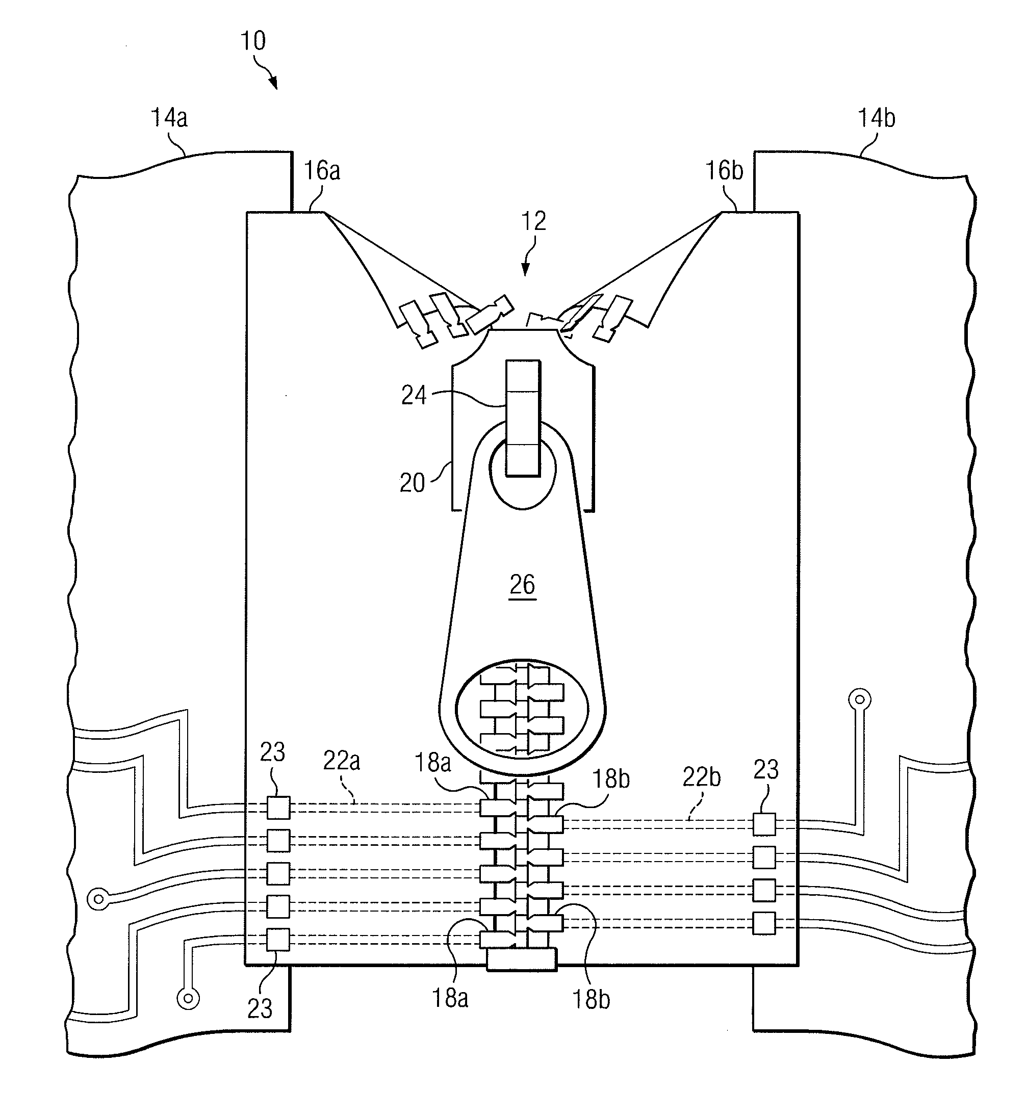
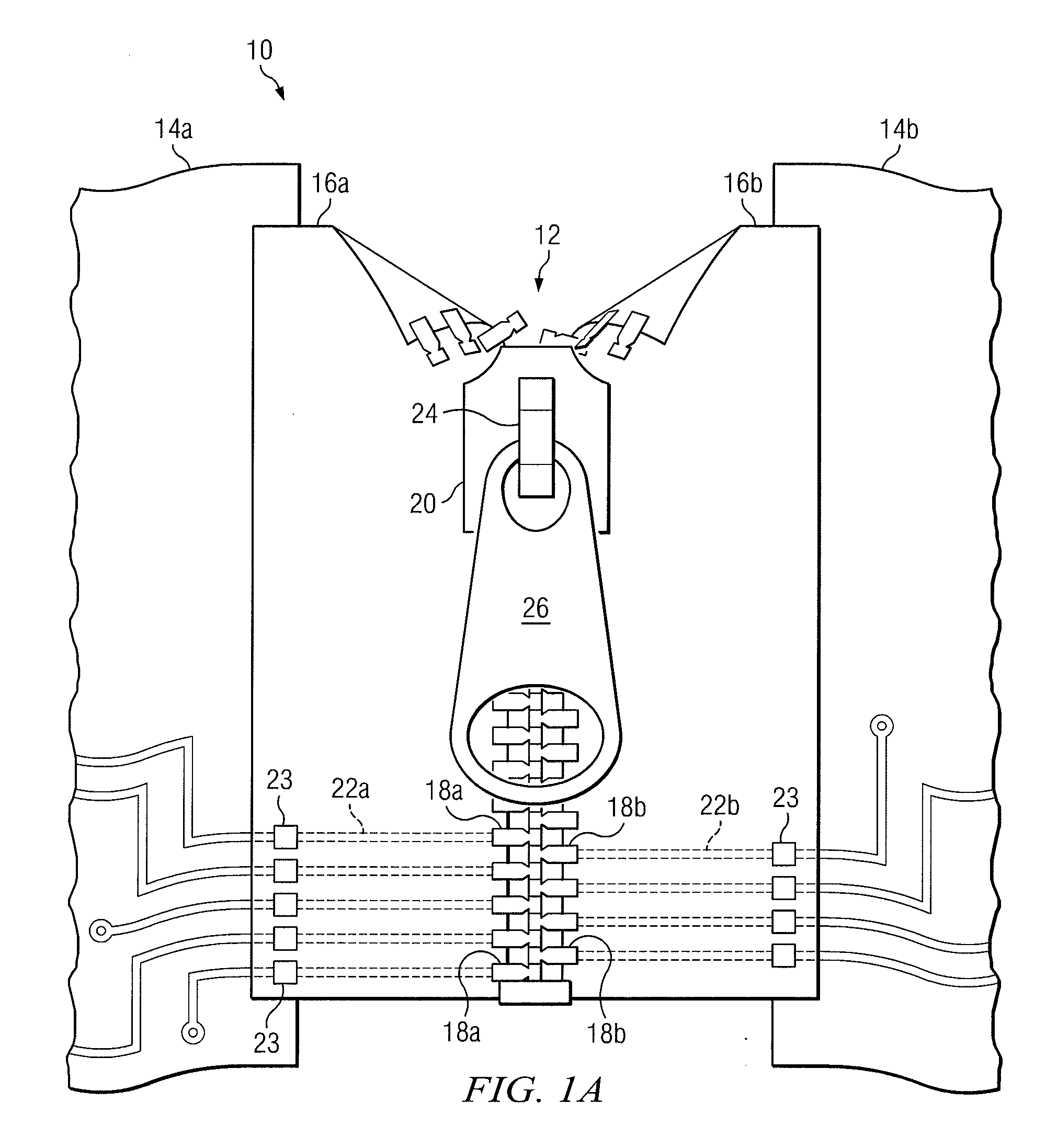
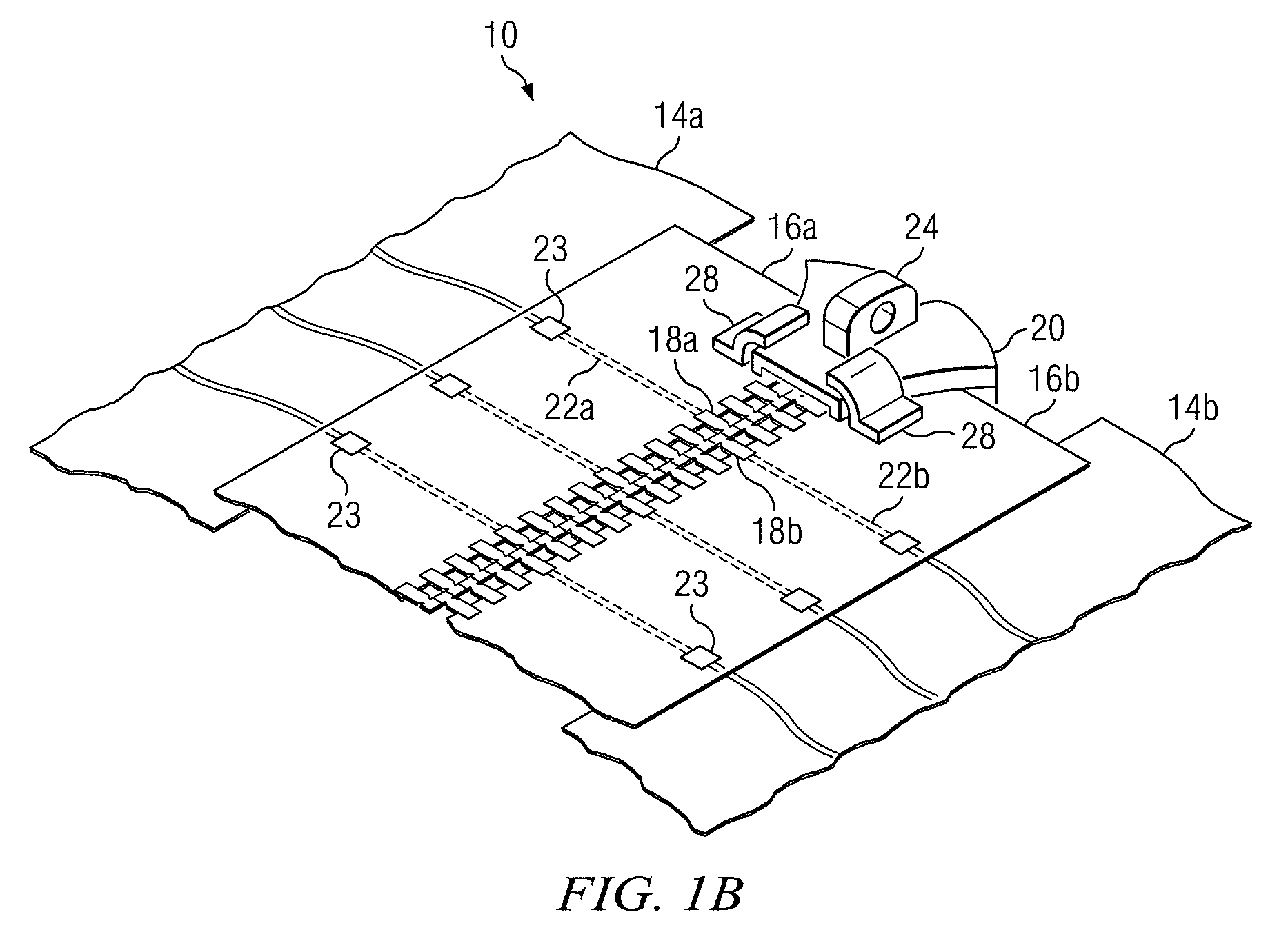
[0013]Complex electrical systems are often configured with multiple subsystems that function together to perform a useful function. These subsystems are usually coupled together using electrical interconnection systems that electrically couple certain nodes of one subsystem to those of another. One particular type of electrical interconnection system includes a flex circuit having one or more copper traces configured on a flexible substrate. The flexibility of the flex circuit provides electrical interconnection between subsystems without constraining the physical layout betwee...


PUM


Abstract

According to one embodiment, an electrical interconnection system includes multiple first electrical contacts and multiple second electrical contacts alternatively meshed together using a slider. The first electrical contacts are configured on a first substrate and electrical coupled to a first electrical circuit, while the second electrical contacts are configured on a second substrate and electrical coupled to a second electrical circuit. When meshed together, the first electrical contacts and second electrical contacts electrically couple the first electrical circuit to the second electrical circuit.

Description

RELATED APPLICATIONS[0001]This application claims priority to U.S. Provisional Patent Application Ser. No. 61 / 200,710, entitled “ELECTRICAL INTERCONNECTION SYSTEM,” which was filed on Dec. 2, 2008. U.S. Provisional Patent Application Ser. No. 61 / 200,710 is hereby incorporated by reference.TECHNICAL FIELD OF THE DISCLOSURE[0002]This disclosure generally relates to electrical devices, and more particularly, to an electrical interconnection system that may be used to electrically couple electrical circuits together.BACKGROUND OF THE DISCLOSURE[0003]Complex electrical systems are often designed to have multiple subsystems that are electrically coupled together to perform some useful function. Each subsystem usually performs a portion of the overall functionality of its electrical system. The design of electrical systems with multiple subsystems may allow designers to accommodate these electrical systems in various types of enclosures. Multiple subsystems may also provide an efficient ap...

Claims


Application Information

Patent Timeline
Patent Type & Authority Applications(United States)
IPC IPC(8): H01R12/14H01R12/78
CPCA44B19/30H01H1/12H01H2001/125H01R4/58H05K3/365H01R12/78H01R12/89H01R13/28H01R12/774
Inventor STRICKLAND, JULIE N.
Owner RAYTHEON CO
Why Eureka
Try Eureka