Wind tunnel for training parachutists

a wind tunnel and parachutist technology, applied in the field of aerodynamics, can solve the problems of long-axis displacement of parachutists, habituation to harmful reflexes, and affect the team's performan

Inactive Publication Date: 2010-06-03
PETRUK VICTOR BORISOVICH
View PDF13 Cites 10 Cited by
  • Summary
  • Abstract
  • Description
  • Claims
  • Application Information

AI Technical Summary

Problems solved by technology

Otherwise, the inequality of the mentioned forces will cause a longitudinal displacement of the parachutist along the axis of the flow and his / her exiting the working zone or encountering the safety net due to the limited working.
The main disadvantage of this equipment is unsatisfactory quality of the flow in the second section that negatively influences the quality of the group acrobatics teams' training and causes the habituation to harmful reflexes, which affect negatively the teams' results in performing the parachute jumps.
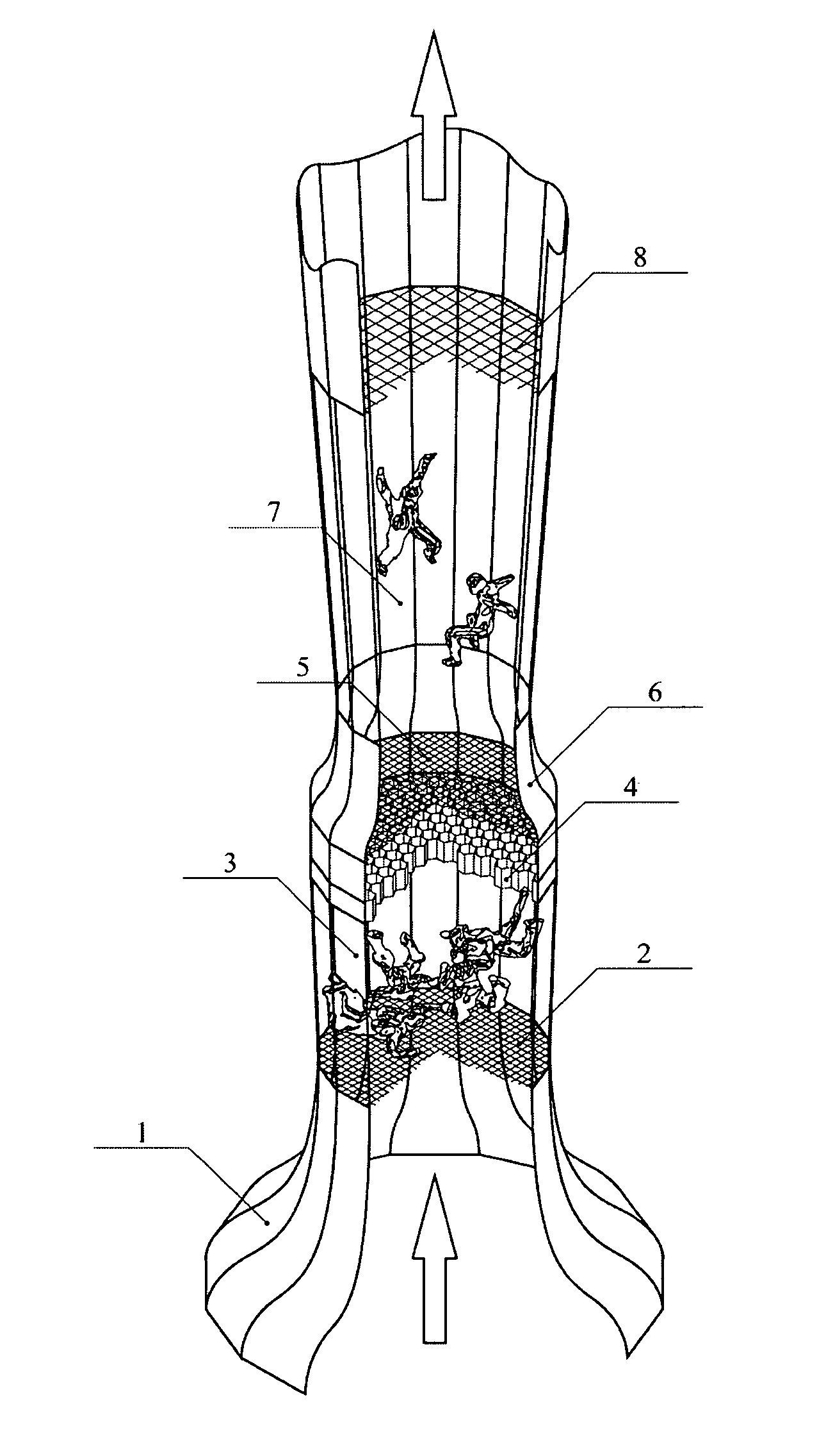
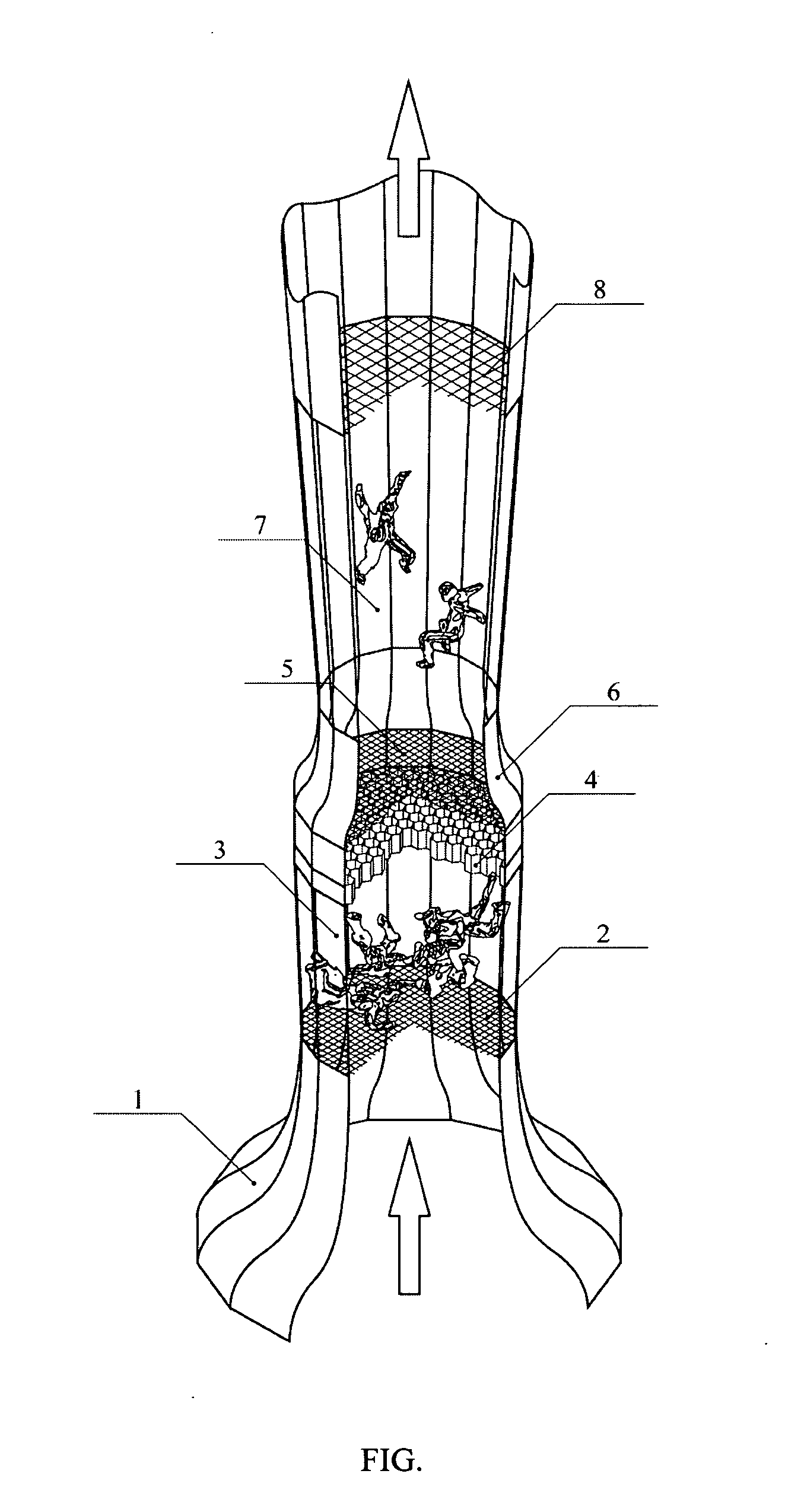
When performing the parachute jump in the free air, the longitudinal gradient is absent and the established reflex habit for its compensation by the increase or decrease of the body's master cross-section causes that during the spinning performance with crossing planes the upper parachutist ascends higher than it is needed and the lower parachutist descends lower than the required level, that leads to vertical dispersion of the parachutists and, consequently, worsens the results.
Secondly, the presence of the initial diffuser section causes the velocity profile change, the boundary layers thicken and the steady speed core diminishes.
Thirdly, resulting from the diffuser having an opening angle, flow velocity vectors' directions within the working section are not parallel.
When performing the parachute jump in the free air the lateral force is absent, and the established reflex habit for its compensation by inclining the body to the centre of the group result in that the team works too densely, “bunches up”, that negatively affects the results of its performance.
One more disadvantage of the mentioned training equipment is excessive hydraulic losses when working in the upper section of the working, because the lower diffuser section unused at this time, the lower safety net, and the honeycomb, placed in the narrowest section of the channel, are the main sources of the hydraulic losses.
The main disadvantage of the mentioned equipment is the placement of ventilators (i.e. fans creating an air pressure difference) in the sections of the channels between working zones and the absence of elements, which can equalize the velocity distribution at the entrance of the working zones.
The presence of the ventilator bushing's wake in the working zone makes the valid training impossible, because getting of the parachutist into the wake, where the dynamic pressure is lower than in the main flow, will cause his / her fall on the safety net.
On the other hand, movement of the parachutist within the working zone without getting into the wake is practically impossible, because it occupies a significant part of the working zone's diameter.
Moreover, the ventilators' bushings, placed in the sections close to the working zones' sections by their areas, with taking into account the flow's squeezing on the bushing, will become sources of significant hydraulic losses.
The main disadvantage of the mentioned wind tunnel is the impossibility to train simultaneously in both working zones (since elements, excluding the getting of the models wake from the first working zone into the second working zone, are absent), resulting in the researches are made in the working zones separately, taking turns.
Therefore, while the research is conducted in one working zone, the flow also passes through the other working zone, not used at the moment, and creates additional unwanted losses, especially in case of working within the first working zone, because the additional squeezing in the intermediate contraction, with the following braking in the contraction after the second working zone increases significantly common hydraulic losses in the contour.
A disadvantage of the mentioned wind tunnel, related to the sportsmen parachutists training, are the absence of a velocity gradient in the working zones (the velocity in the steady speed core is the same in any working zone's crossing).
Another disadvantage is the impossibility of simultaneous work of the parachutists in the first and in the second working zones, resulting from the significantly different velocities.

Method used


Image

  • Wind tunnel for training parachutists
  • Wind tunnel for training parachutists

Examples


Embodiment Construction

[0045]While the invention may be susceptible to embodiment in different forms, there is shown in an appended drawing figure (FIG.), and will be described in detail herein, a specific embodiment of the present invention, with the understanding that the present disclosure is to be considered an exemplification of the principles of the invention, and is not intended to limit the invention to that as illustrated and described herein.

[0046]The concept of the invention is graphically illustrated on the FIG. in the form of a diagram of the inventive wind tunnel.

[0047]The wind tunnel comprises: an entrance confusor 1, an entrance safety net 2, a first working zone 3, a honeycomb 4, an intermediate safety net 5, an intermediate confusor 6, a second working zone 7 and an exit safety net 8.

[0048]The wind tunnel operates in the following way: a ventilator set (it is not depicted on the FIG.) creates a pressure differential, which causes the air to move within the tunnel contour upward. In the e...


PUM


Abstract

A wind tunnel is provided usable for training of sportsmen-parachutists and entertainment purposes. The tunnel comprises a channel, including sequentially arranged and interconnected components: an input confusor, a first working zone, an intermediate confusor, and a second working zone. The working zones are shaped as diffusers, having different longitudinal flow speed gradients, so that the working zone having the lesser longitudinal speed gradient is shorter, whereas the working zone having the greater longitudinal speed gradient is longer. A honeycomb is arranged between the working zones. The entrances and exits of the working zones are equipped with safety nets. The structural design of the tunnel makes it possible to simultaneously train parachutists for team acrobatics and artistic types of parachuting under conditions, maximally adapted to a given type of training, thereby improving a training quality and substantially increasing the tunnel's cost effectiveness.

Description

CROSS-REFERENCE TO RELATED APPLICATIONS[0001]This application is a U.S. national phase application of a PCT application PCT / UA2006 / 000042 filed on 29 Jun. 2006, published as WO2007008184, whose disclosure is incorporated herein in its entirety by reference, which PCT application claims priority of a Ukrainian patent application UA2005 / 06866 filed on 12 Jul. 2005.FIELD OF THE INVENTION[0002]The invention relates to aerodynamics, particularly to wind tunnels and can be used as training equipment for parachutists and for entertainment.BACKGROUND OF THE INVENTION[0003]The known parachuting disciplines related to free fall can be divided into those that are performed with a constant rate of fall (about 50-55 m / s) and with a variable rate of fall (approximately within 45-70 m / s). The first ones include group acrobatics and beginner parachutist training (acquisition of stable fall skills). The second ones include artistic forms of the parachuting, such as: ‘free fly’, ‘free style’ and othe...

Claims


Application Information

Patent Timeline
Patent Type & Authority Applications(United States)
IPC IPC(8): A63G31/00
CPCA63G31/00G01M9/02B64D23/00A63G2031/005
Inventor PETRUK, VICTOR BORISOVICH
Owner PETRUK VICTOR BORISOVICH
Why Eureka
Try Eureka