
Construction safety hanger

a construction safety and hanger technology, applied in the field of construction safety hangers, can solve the problems of limited freedom of movement of workers, inability to produce, and inability to meet the needs of workers, and achieve the effect of cost saving and cost saving

Inactive Publication Date: 2012-03-08
LARKIN JAMES
View PDF0 Cites 18 Cited by
  • Summary
  • Abstract
  • Description
  • Claims
  • Application Information

AI Technical Summary

Benefits of technology

[0011]It is another object of the invention to provide a safety hanger system that provides requisite safety at construction sites while maximizing the flexibility and range of movements of construction workers at the site.
[0013]It is yet another object of the invention to provide a safety hanger system for construction sites that provides safety not only to individual tethered workers but to all workers that operate within a given zone or perimeter.
[0016]It is yet a further object of the invention to provide a safety hanger that can be re-used and need not be destroyed after use.
[0017]It is an additional object of the invention to provide a safety strap and system using the same that provides optimal safety to workers that is inexpensive to produce and cost efficient.

Problems solved by technology

During the initial phases of construction, when buildings are relatively open and the walls or other protective barriers are not yet in place, workers can accidently fall with potential grave injury.
However, such safety belt, once secured to a post, railing or ladder renders the individual relatively immobile and with a limited maneuverability.
However, as with numerous other prior art safety devices, there is a limitation on the freedom of movement of the worker, since the worker is essentially tethered to a relatively short length of strap.

Method used


Image

  • Construction safety hanger
  • Construction safety hanger
  • Construction safety hanger

Examples


Embodiment Construction

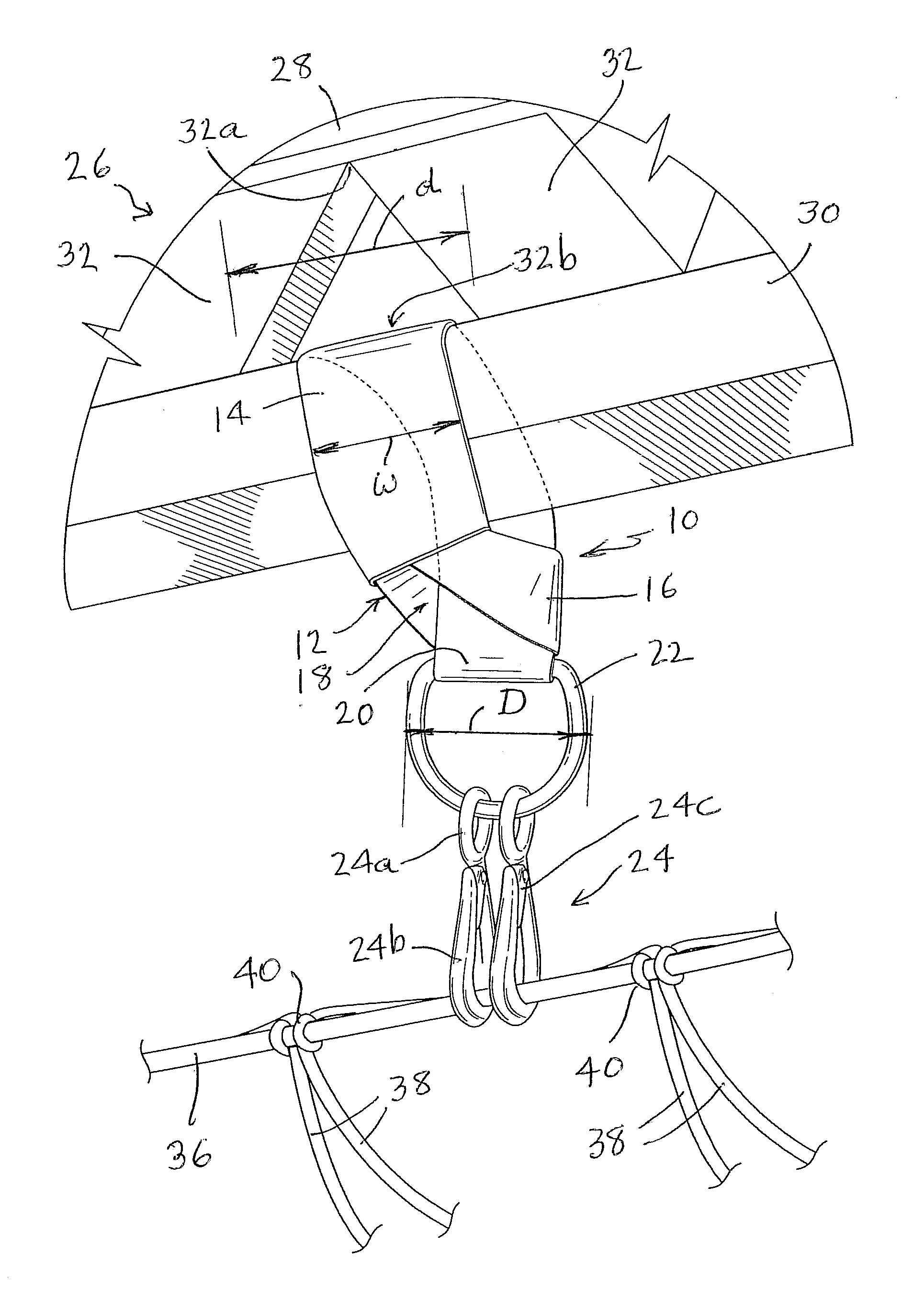
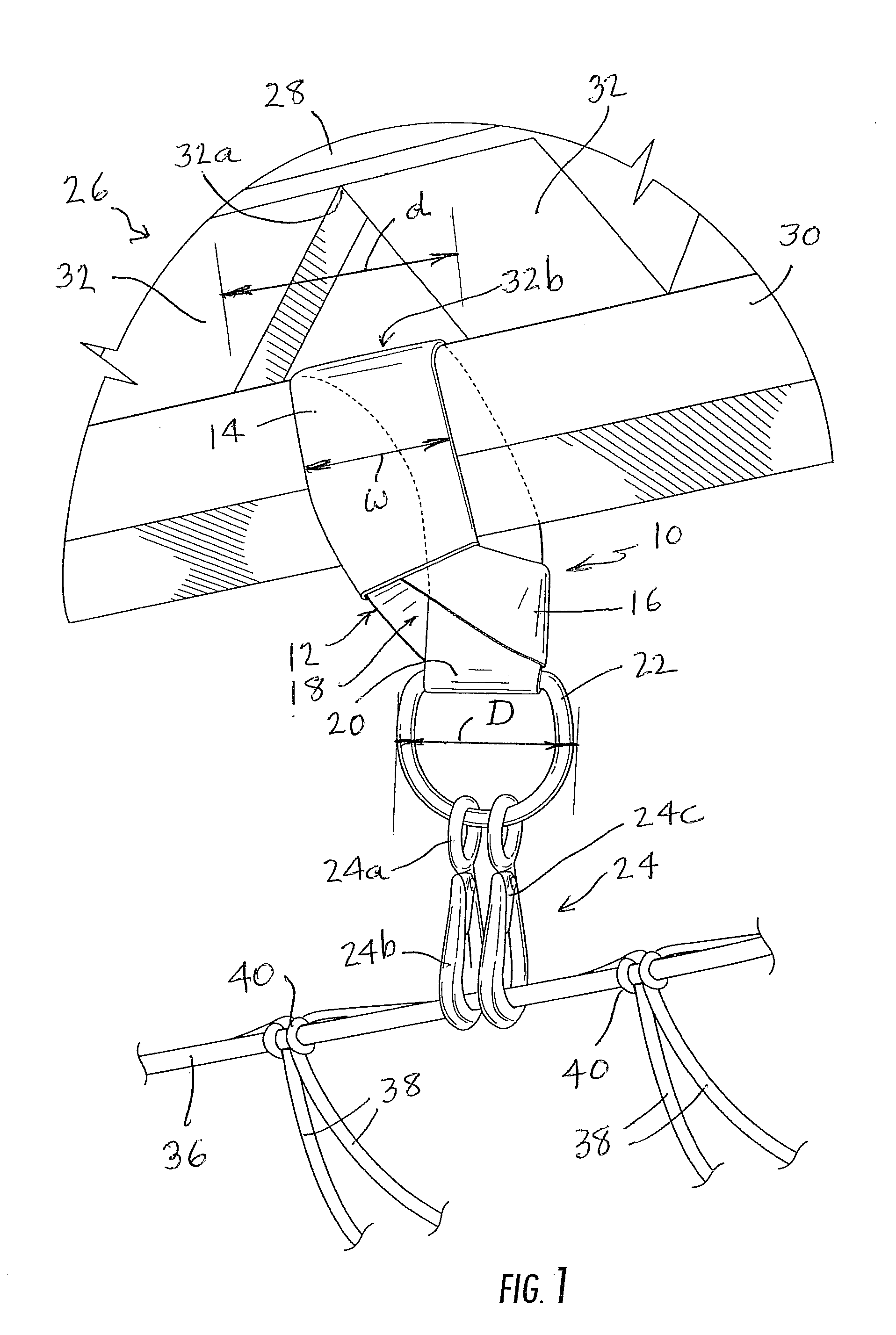
[0022]Referring now specifically to the Figures, in which the identical or similar parts are designated by the same numeral numbers throughout, and first referring to FIG. 1, a safety hanger in accordance with the present invention is generally designated by the reference numeral 10.

[0023]The hanger 10 is in a nature of strap 12 made, for example, of highly durable nylon. However, other strong suitable materials can be used. Optionally, a protective sleeve 14 is provided to cover the strap while exposing the free ends thereof. The protective sleeve 14 provides a low friction interface between the strap and the support member on which it is mounted to ensure that the strap can be readily tightened without creating significant friction between the strap and support member. The strap 12 is provided with two ends, one free end 16 being provided with a closed loop that forms an opening 18. The other end 20 of the strap is likewise provided with a closed loop end for capturing a D-ring or...


PUM

PropertyMeasurementUnit
Shapeaaaaaaaaaa
Frictionaaaaaaaaaa

Abstract

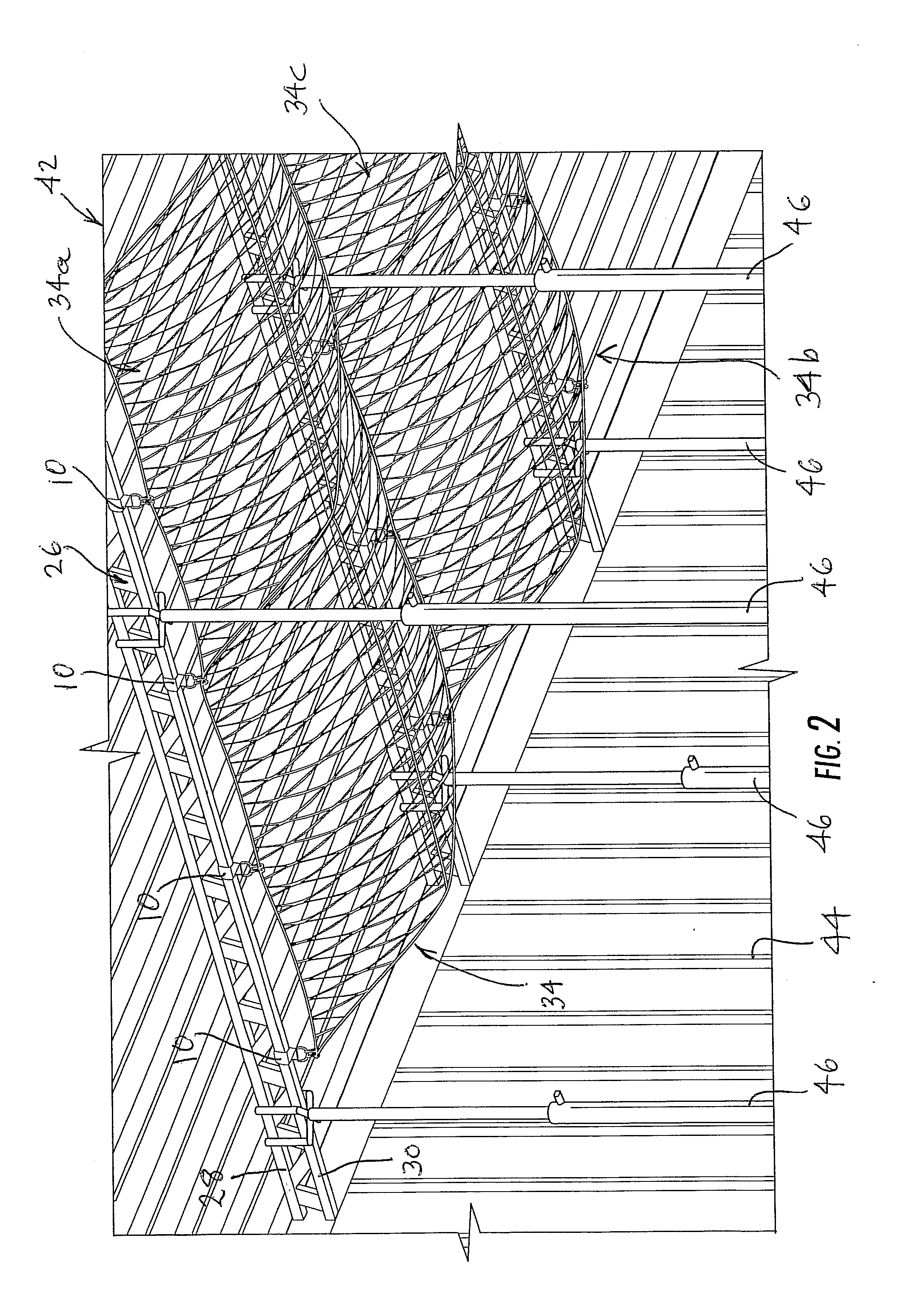
A safety hanger system for attachment to horizontal members of stringers or other support members forming a subfloor include a plurality of safety hanger straps each of which is provided with closed loop ends. Rigid retaining members such as D-rings are linked through one of said loop ends at one end of each of the straps. Snap hooks are supported on the retaining members. The safety hangers are attachable in spaced relationship to the stringers with at least one snap-hook positioned to engage a safety net below the adjacent stringers to catch a worker that slips through a subfloor under which the net is placed, whereby workers have freedom of movement above the subfloor without the need to be tethered by lanyards to any given fixed point. A method is disclosed for attaching the safety hanger straps to the stringers and for securing safety net(s) to the snap hooks.

Description

CROSS REFERENCE TO RELATED APPLICATION[0001]This application is related to Provisional Patent application Ser. No. 61 / 380,506 filed on Sep. 7, 2010.BACKGROUND OF THE INVENTION[0002]1. Field of the Invention[0003]The invention generally relates to the filed of construction and. more specifically, to a construction safety hanger.[0004]2. Description of the Prior Art[0005]It has always been a considerate hazard safety to workman involved in a construction industry, such as steel frames for buildings, bridges and other tall structures. Because of the serious hazards that construction workers are exposed to the Occupational Safety and Health Administration (OSHA) has enacted numerous health and safety standards and regulations. One such set of regulations involves fall protection. During the initial phases of construction, when buildings are relatively open and the walls or other protective barriers are not yet in place, workers can accidently fall with potential grave injury. OSHA had i...

Claims


Application Information

Patent Timeline
IPC IPC(8): F16M13/02B23P11/00A62B35/00
CPCY10T29/49947E04G21/3266
Inventor LARKIN, JAMES
Owner LARKIN JAMES
Learn More