Garlic Press

Inactive Publication Date: 2010-06-10
HANSEL DOUGLAS +2
View PDF14 Cites 3 Cited by
  • Summary
  • Abstract
  • Description
  • Claims
  • Application Information

AI Technical Summary

Benefits of technology

[0008]The above object and other objects of the present invention which will be understood upon a reading of the following specification and claims are achieved by a handle operated garlic press having a pressure chamber which is open on front side which allows easier insertion of items to be crushed, and also allows a perforated bottom plate in the pressure chamber to be pivoted out and exposed for easier cleaning.
[0009]Access to the pressure chamber is also made easier by not being located between the handles, but instead by a geometry in which the handles do not extend across the pressure chamber as in many of the conventional garlic presses.

Problems solved by technology

In conventional designs, significant effort is required to squeeze the handles with sufficient force so as to push the garlic through the bottom plate holes.
If the pressure applied is insufficient some of the crushed garlic may not be forced through the holes and remains on the bottom plate and is then cleaned out with the garlic clove skin and wasted.
The pressure chamber being completely enclosed by the surrounding walls and located between the two operating handles is not easily accessed to load garlic cloves therein, and the recessed perforated bottom plate is also difficult to keep clean.

Method used


Image

  • Garlic Press
  • Garlic Press
  • Garlic Press

Examples


Embodiment Construction

[0024]In the following detailed description, certain specific terminology will be employed for the sake of clarity and a particular embodiment described in accordance with the requirements of 35 USC 112, but it is to be understood that the same is not intended to be limiting and should not be so construed inasmuch as the invention is capable of taking many forms and variations within the scope of the appended claims.

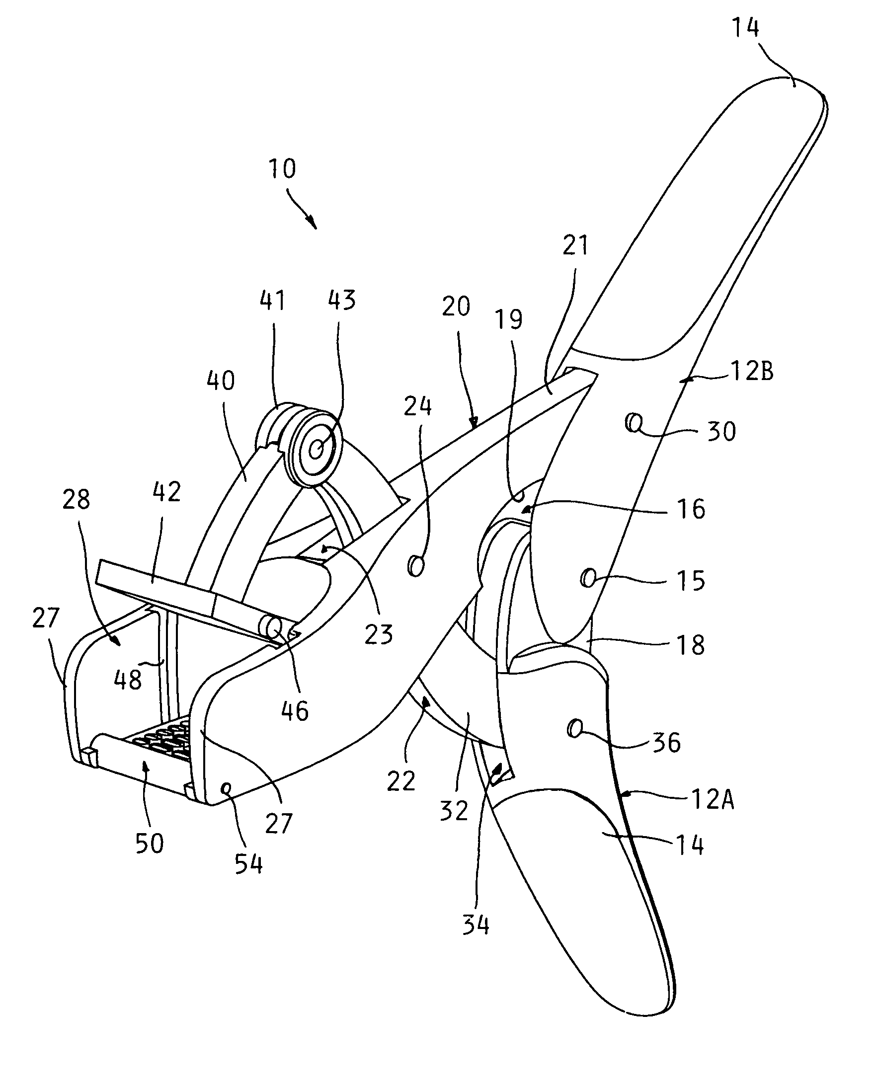
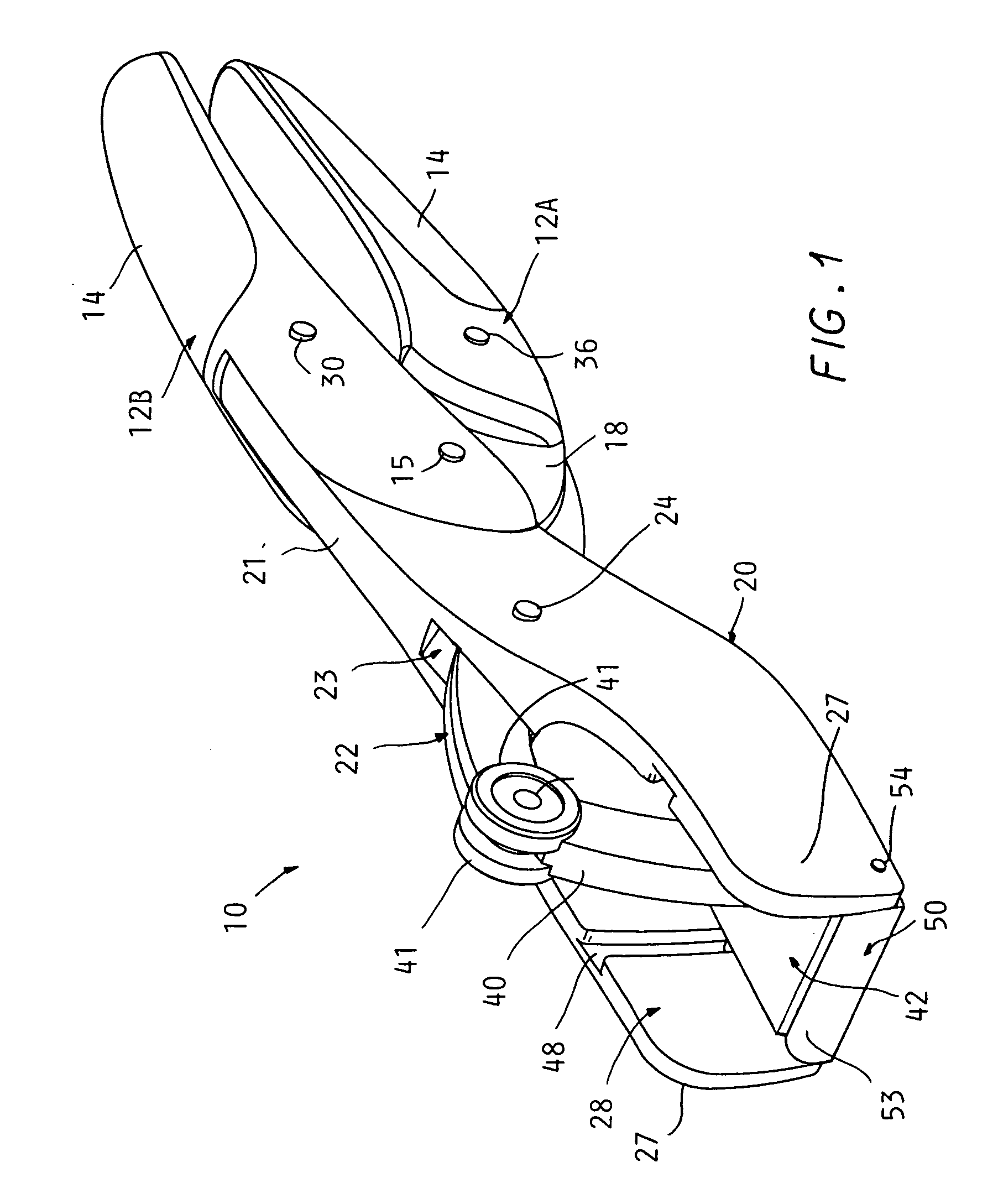
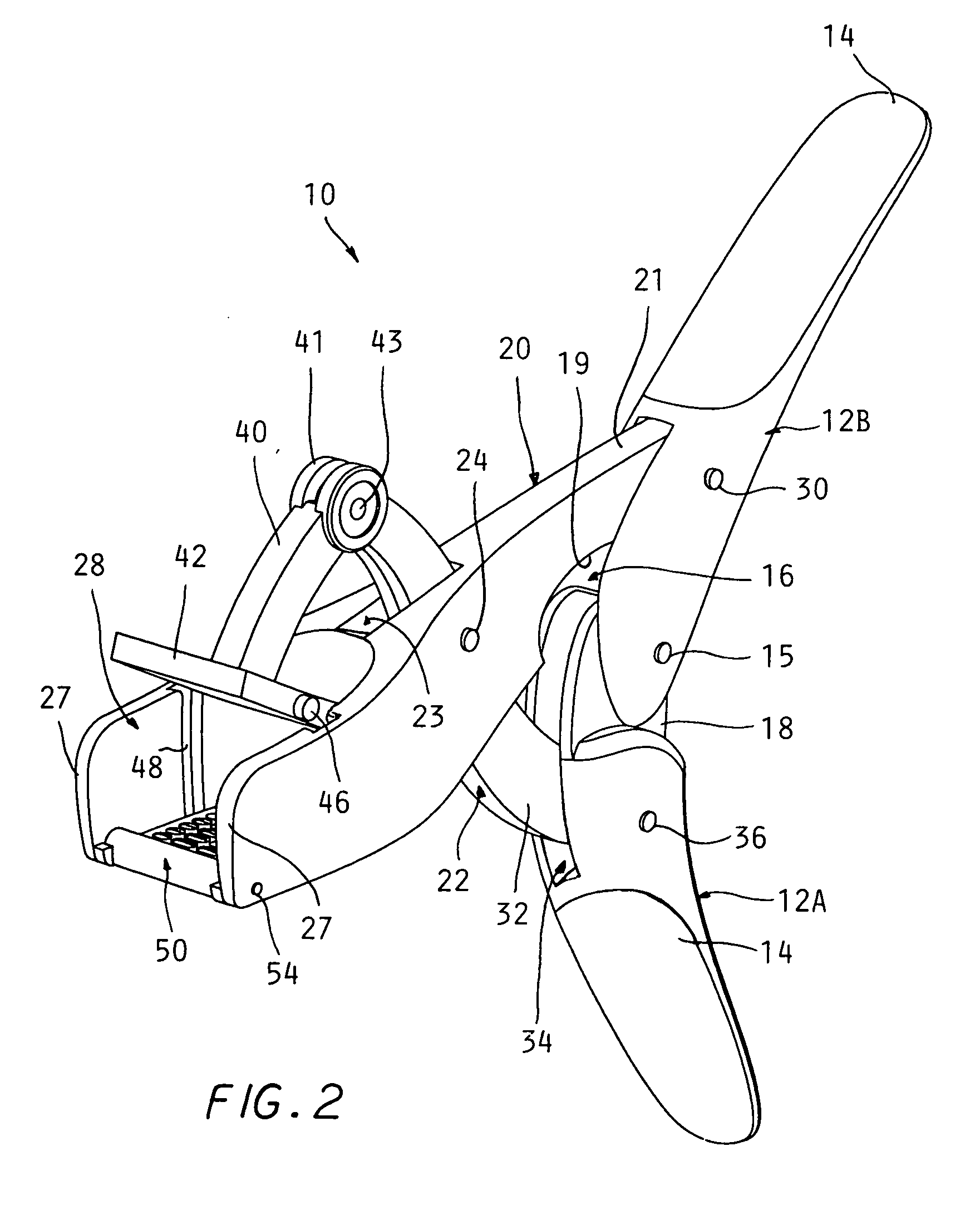
[0025]Referring to the drawings and particularly FIGS. 1 and 2, a garlic press 10 according to the present invention is shown which includes a pair of generally elongate handles 12A, 12B, which may be constructed of cast aluminum, steel, stainless steel or plastic or other material and provided with soft elastomeric pads 14.

[0026]The handles 12A, 12B have interfit portions at one end which are pivotally connected to each other by a pivot pin 15. Upper handle 12B is formed with a clevis opening 16 and handle 12A with a reduced thickness end 18 fit therein with sufficient ...


PUM


Abstract

A hand operated garlic press includes a pair of crossed levers operated by pivoted together handles combined with the cross levers to easily create a strong crushing pressure in a pressure chamber into which garlic cloves are placed through an open front end of the chamber.

Description

CROSS REFERENCE TO RELATED APPLICATIONS[0001]This application claims the benefit of U.S. provisional patent application No. 61 / 201,450 filed on Dec. 10, 2008.BACKGROUND OF THE INVENTION[0002]This application concerns manually operated garlic presses which are used to crush garlic cloves to obtain finely divided fresh garlic for use in cooking.[0003]Such presses have long been in use and typically are of a “nutcracker” design, wherein a pair of handles are hinged at one end and connected to a pressure plate located between the handles and forced down into a pressure chamber, also located between the handles. The pressure chamber is defined by a perforated bottom plate and surrounding side walls. The pressure plate is advanced down into the pressure chamber by squeezing the handles together which crushes the garlic inserted beneath the pressure plate and forces it through the bottom plate holes.[0004]In conventional designs, significant effort is required to squeeze the handles with s...

Claims


Application Information

Patent Timeline
IPC IPC(8): B30B7/00
CPCA47J19/06
Inventor HANSEL, DOUGLASHAWKER, CHRISTOPHER L.RENALDO, SOMMER
Owner HANSEL DOUGLAS
Why Eureka
Try Eureka