Mounting rail and power distribution system for use in a photovoltaic system

a photovoltaic system and mounting rail technology, applied in the direction of insulated conductors, cables, coupling device connections, etc., can solve problems such as installation errors, and achieve the effect of simplifying the installation process of a pv system

Inactive Publication Date: 2010-06-10
ENPHASE ENERGY
View PDF47 Cites 55 Cited by
  • Summary
  • Abstract
  • Description
  • Claims
  • Application Information

AI Technical Summary

Benefits of technology

[0007]In order to simplify the installation process of a PV system, there is...

Problems solved by technology

This installation process is complex, labo...

Method used


Image

  • Mounting rail and power distribution system for use in a photovoltaic system
  • Mounting rail and power distribution system for use in a photovoltaic system
  • Mounting rail and power distribution system for use in a photovoltaic system

Examples


Embodiment Construction

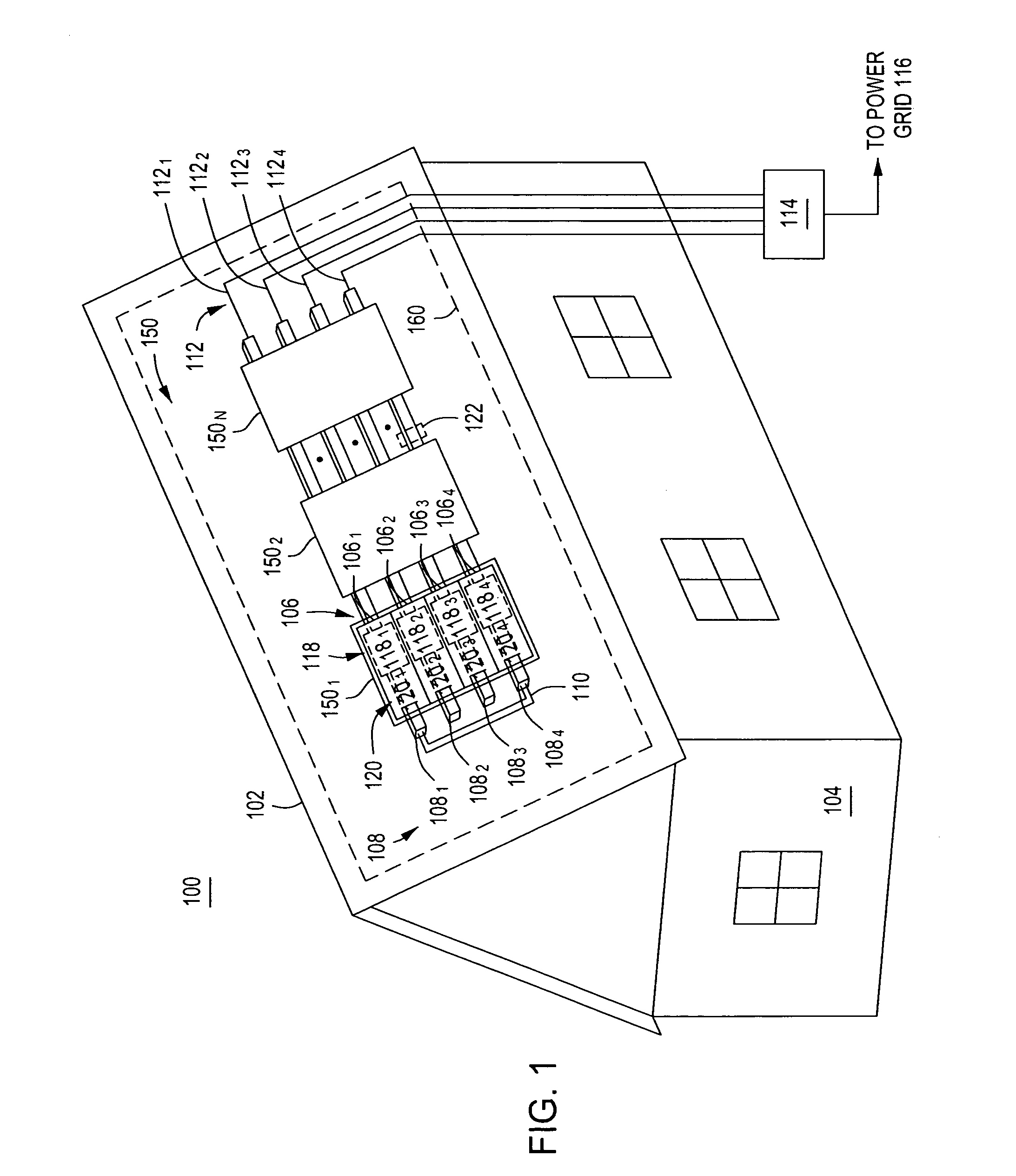
[0017]FIG. 1 is a block diagram of a system 100 for coupling generated power to an output load in accordance with one or more embodiments of the present invention. The system 100 comprises a building 104, a roof 102 of the building, and a photovoltaic (PV) array 160 mounted upon the roof 102. Such rooftop mounting of PV arrays is common; however, the PV array 160 may be mounted in other locations utilizing various embodiments of the present invention.

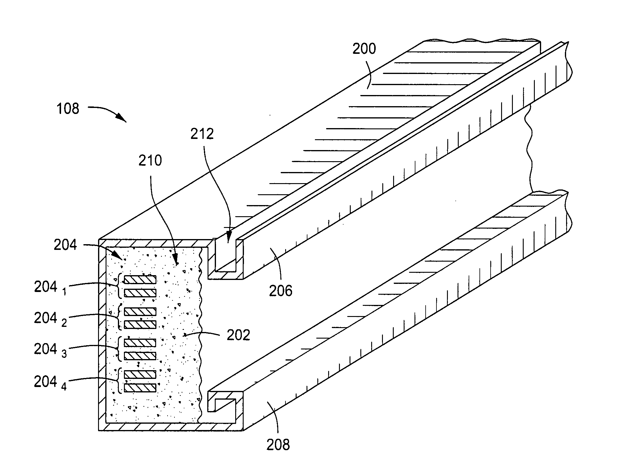
[0018]The PV array 160 comprises a mounting assembly 110, integrated PV module mounting rails 1081, 1082, 1083, and 1084, collectively referred to as mounting rails 108, and a plurality of PV panels 1501, 1502, . . . , 150n, collectively referred to as PV panels 150. The mounting assembly 110 supports the mounting rails 108, upon which the PV panels 150 are mounted in a horizontal arrangement.

[0019]Each PV panel 150 comprises a PV module 1201, 1202, 1203, and 1204, collectively referred to as PV panels 120, arranged vertically within th...


PUM

PropertyMeasurementUnit
Lengthaaaaaaaaaa
Poweraaaaaaaaaa
Phaseaaaaaaaaaa

Abstract

Apparatus for coupling generated power to an output load. The apparatus comprises a first mounting rail, adapted for electrically coupling a power element to the output load. The first mounting rail comprises a frame defining a cavity; an insulative material disposed within at least a portion of the cavity; and a first at least two conductors, encapsulated within the insulative material, adapted for coupling power from the power element to the output load.

Description

CROSS-REFERENCE TO RELATED APPLICATIONS[0001]This application claims benefit of U.S. provisional patent application Ser. No. 61 / 200,845, filed Dec. 4, 2008, which is herein incorporated in its entirety by reference.BACKGROUND OF THE INVENTION[0002]1. Field of the Invention[0003]Embodiments of the present invention generally relate to power distribution and, more particularly, to a mounting rail and AC power distribution system for use in a photovoltaic system.[0004]2. Description of the Related Art[0005]Photovoltaic (PV) systems comprise a plurality of PV modules arranged in an array and coupled to one or more DC-to-AC inverters. One particular type of PV system uses a plurality of PV modules and a plurality of inverters, where each PV module is coupled to an inverter forming an integrated PV module. In such a system, the DC power produced by each PV module is converted to AC power at a location proximate the PV module (e.g., on a rooftop). The AC power generated by each inverter is...

Claims


Application Information

Patent Timeline
IPC IPC(8): H01B7/00H01R4/24H01R43/00
CPCH01L31/02008H01L31/02021H01R4/2404H01R13/5216Y10T29/49117H02G5/04Y02B10/12Y02E10/50H02S20/23H01R25/14Y02B10/10
Inventor DARGATZ, MARV
Owner ENPHASE ENERGY
Why Eureka
Try Eureka