Machining score lines in a rupture disc using laser machining

a technology of laser machining and rupture disc, which is applied in the direction of manufacturing tools, functional valve types, mechanical equipment, etc., can solve the problems of reducing the accuracy of the machining, and reducing the service life of the disc, so as to reduce the heat affected zone, the effect of maximizing the peak power of the laser and reducing the heat affected zon

Inactive Publication Date: 2010-06-10
CONTINENTAL DISC CORP
View PDF39 Cites 49 Cited by
  • Summary
  • Abstract
  • Description
  • Claims
  • Application Information

AI Technical Summary

Benefits of technology

[0015]In a further embodiment, a method of forming a score line in a rupture disc using a laser is provided. The method includes determining score line requirements for the rupture disc and selecting a laser system having a wavelength that enables absorption of the laser energy by the disc material, a pulse duration that maximizes a peak power of the laser, a pulse repetition rate that reduces a heat affected zone of the rupture disc during ablation, a focal spot diameter, and the speed of the relative motion between the laser beam and the disc that achieves the precision and tolerances of the score line requirements. The method further includes adjusting at least one of an optical output power of the laser, a pulse repetition rate of the laser, a focal spot diameter of the laser beam, and the speed of the relative motion between the laser beam and the disc to determine a laser configuration capable of achieving the score line requirements. The score line is ablated in the rupture disc using the laser configuration to remove material from the rupture disc as vapor without melting or oxidizing disc material adjacent the material being removed.

Problems solved by technology

Typically, forming score lines using metal score dies causes changes in the grain structure and density of the metal in the area surrounding the score line thereby creating residual stresses in the disc.
The residual stresses negatively affect the capacity of the disc to withstand multiple cyclic loads thereby reducing the service life of the disc.
Moreover, metal scoring is difficult to control with high precision resulting in a significant increase in setup time and other non-value added costs during production.
Unfortunately, this process requires multiple successive operations and is therefore more expensive and time consuming than applying a laser beam directly to the disc material to create the score lines.
However, as described in U.S. Patent Application Publication No. 2006 / 0237457 at paragraphs [0012-0016], this process can roughen the exposed surface of the disc and increase stress on the score line during cycling thereby reducing the disc's service life.
Further, the roughened score line is more susceptible to corrosive effects thereby further decreasing the service life of the disc.
Still further, chemical etching also involves the cumbersome handling of hazardous materials.
In addition, the costs of etching make this process impractical for commercial application.
Accordingly, there are few practical types of lasers available for material machining.
U.S. Patent Application Publication No. 2006 / 0237457 teaches in paragraph that the proposal of using a laser beam directly on a disc for forming score lines has “not proved commercially satisfactory for a number of reasons.” Specifically, “the reflectivity of the metal makes it difficult to control the penetration of the laser into the thickness of the metal”.
“Furthermore, lasers significantly heat and burn the disc, oxidize the material and change the metallurgy of the metal.
Discs having score lines burned by a laser have been found to be unsatisfactory in use, not only from the standpoint of unreliable openings at required pressure relief values, but also having undesirable cycle life”.

Method used


Image

  • Machining score lines in a rupture disc using laser machining
  • Machining score lines in a rupture disc using laser machining
  • Machining score lines in a rupture disc using laser machining

Examples


Embodiment Construction

[0031]The following description of the preferred embodiment(s) is merely exemplary in nature and is in no way intended to limit the scope of the present invention, its applications, or uses.

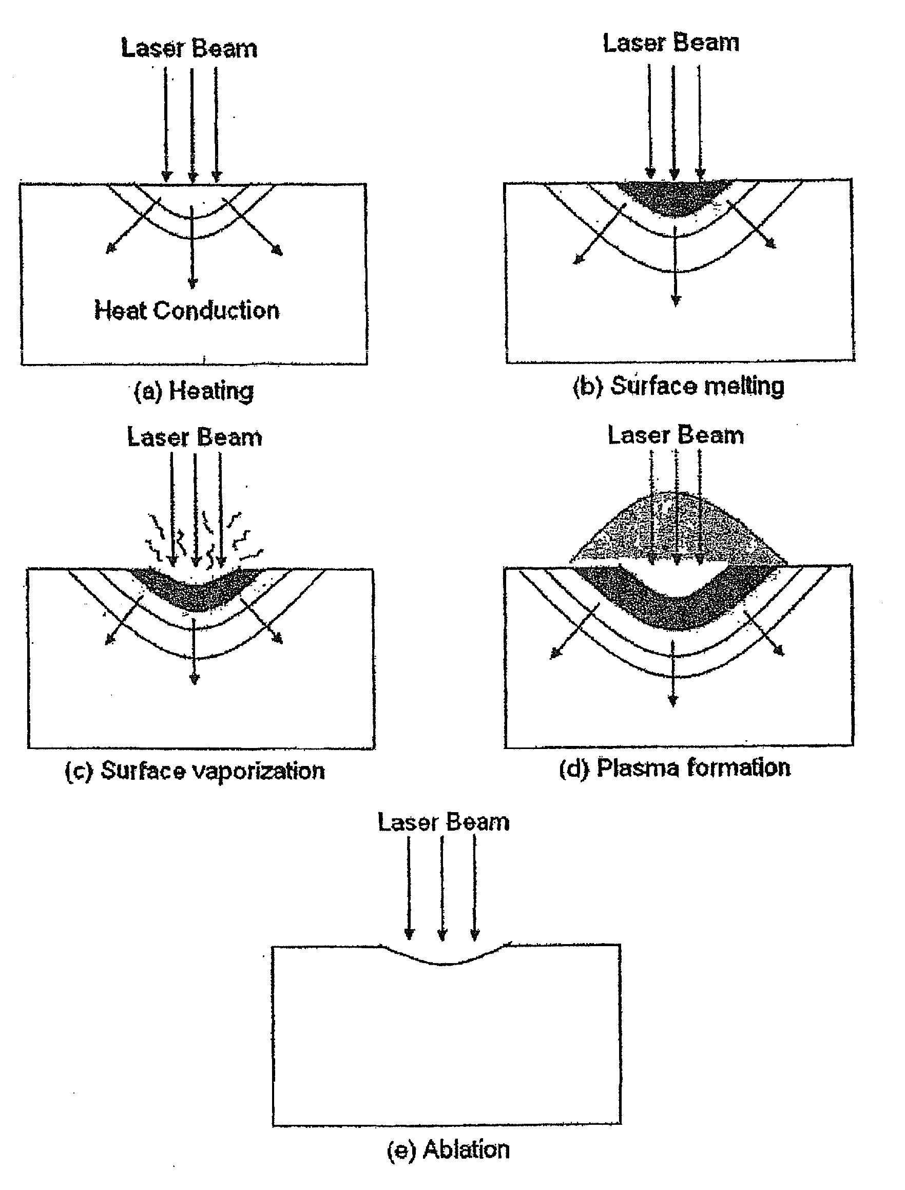
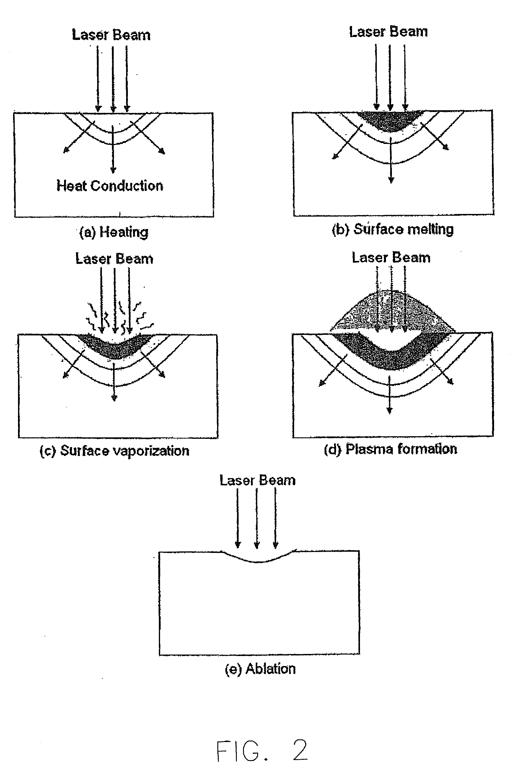
[0032]The present invention involves the utilization of a laser beam to remove material from rupture discs to create lines of weakness (score lines) of various widths, depths and configurations. The following method can be utilized to score lines of weakness in any type of rupture disc including tension-type disc domes, flanges, diaphragms and panels, reverse-acting disc domes, flanges, diaphragms and panels, and any other type of rupture device. Rupture disc as used herein throughout this application is intended to include all types of forward acting tension type rupture discs, reverse-acting rupture discs, vent panels, explosion vents, explosion panels, rupture panels, and rupture diaphragms regardless of their shape and configuration including dome shaped and flat discs.

[0033]Laser machining c...


PUM

PropertyMeasurementUnit
wavelengthaaaaaaaaaa
speedaaaaaaaaaa

Abstract

A method of forming a score line in a rupture disc using a laser is provided, wherein the method includes selecting a wavelength for the laser that maximizes absorption of the laser radiation by the disc material, selecting a pulse duration for the laser that maximizes a peak power of the laser, selecting a pulse repetition rate for the laser that reduces a heat affected zone of the rupture disc during ablation, and selecting the speed of relative motion between the laser and the rupture disc. The score line is ablated in the rupture disc using the laser to remove material from the rupture disc as vapor without melting or oxidizing disc material adjacent the material being removed.

Description

CROSS-REFERENCE TO RELATED APPLICATION[0001]This application is a continuation-in-part application of U.S. patent application Ser. No. 12 / 331,611, filed Dec. 10, 2008, the entire contents of which are hereby incorporated by reference in their entirety.BACKGROUND OF THE INVENTION[0002]The present invention relates generally to a method of machining lines of weakness in a rupture disc and, more particularly, to a method of machining score lines in a rupture disc using laser technology.[0003]Systems and vessels that contain a pressurized fluid often include rupture discs that relieve the system in the event of over pressurization. Rupture discs may take on a variety of shapes and configurations depending upon the specific application such as a dome shaped disc or a substantially flat shaped disc and such discs are generally placed in a vent or pressure vessel to prevent flow of the fluid through the vent until the disc ruptures. Specifically, as a system becomes over-pressurized and re...

Claims


Application Information

Patent Timeline
Patent Type & Authority Applications(United States)
IPC IPC(8): B23K26/00
CPCB23K26/063B23K26/367F16K17/16B23K2203/02B23K2203/08B23K2201/18B23K26/0622B23K26/364B23K2101/18B23K2103/02B23K2103/05B23K2103/08B23K2103/16B23K2103/26B23K2103/42B23K2103/52
Inventor MOZLEY, ROBERT M.HERNANDEZ, GABRIEL
Owner CONTINENTAL DISC CORP
Why Eureka
Try Eureka