Emission free integrated gasification combined cycle

a gasification combined cycle and gasification reactor technology, applied in the direction of combustible gas production, combustible gas purification/modification, hydrogen separation using liquid contact, etc., can solve the problems of less than about 2 vol % of nitrogen in the product, and higher than normal emissions of contaminants such as sulfur, so as to minimize nox, reduce nitrogen oxides, and maximize the destruction efficiency of volatile compounds

Inactive Publication Date: 2010-04-01
HYDROGEN ENERGY INT
View PDF6 Cites 17 Cited by
  • Summary
  • Abstract
  • Description
  • Claims
  • Application Information

AI Technical Summary

Benefits of technology

[0024]The reducing stream, which typically contains flammable gas with high heating value which can be greater than about 50 BTU / SCF (1869 kilojoules / scm) and oxygen content of less than about 1.0 vol %, is then passed to a vent gas combustor (“VGC”) and combusted in a controlled environment at a combustion nozzle within the VGC. The VGC is a pollution controlled combustor device with a combustion zone within a refractory lined vessel compartment, equipped with fuel nozzles designed for low nitrogen oxides (NOx) production. The combustion residence time is designed for optimum destruction efficiency of volatile compounds and minimization of pollutants, such as carbon monoxide (“CO”), particulates matter (“PM”), and NOx. For this application, other units such as an incinerator, aux boiler and duct firing with the HRSG can be used in place of the vent gas combustor. All such devices will require downstream equipment such as a selective catalytic reduction (“SCR”) reactors, having selective catalysts to minimize NOx, and CO catalytic oxidation reactors to reduce CO emissions and equipment to minimize PM emissions.
[0025]The oxidizing stream, which typically contains only a trace amount of flammable gas, and can contain an oxygen content of greater than about 1.0 vol %. This oxidizing stream is passed to the VGC and introduced into the VGC at a point downstream of the combustion nozzle in the combustion chamber. Both of these reducing and oxidizing streams are combusted under conditions such that the production of nitrogen oxides is reduced. These conditions include the use of commercially available low NOx burner tips that possess enhanced gas mixing features. As mentioned above, the flue gas from VGC is then passed to a catalytic unit that carries out the oxidation of carbon monoxide to carbon dioxide and a selective catalytic reduction to further reduce the nitrogen oxides content of the VGC flue gas to an acceptable level as mandated by air quality regulatory governmental agencies. The flue gas from the VGC can optionally be further cooled by heat exchange to produce steam, or by water quench to produce a cool flue gas stream leaving a stack at a significantly lower temperature than the combustion zone temperature. Such cooling reduces the heat-affected zone of the flue gas emitting from the stack more so than a heat-affected zone created by the uncontrolled combustion in a flare stack.

Problems solved by technology

Third, nitrogen in the product is limited to less than about 2 vol % since excessive amounts of nitrogen may significantly inhibit EOR and permanent sequestration of CO2.
As is well known to those skilled in the art, this results in higher than normal emissions of contaminants such as sulfur.
Accordingly, the start-up of a partial oxidation gas generator presents special challenges, including dealing with the contaminant emissions.
The radiation and the heat affected zone of a flare can extend to a radius of significant size deleteriously affecting neighbors.

Method used


Image

  • Emission free integrated gasification combined cycle
  • Emission free integrated gasification combined cycle
  • Emission free integrated gasification combined cycle

Examples


Embodiment Construction

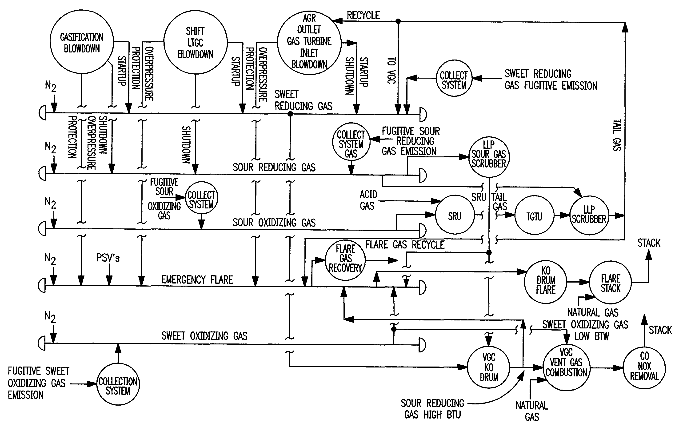
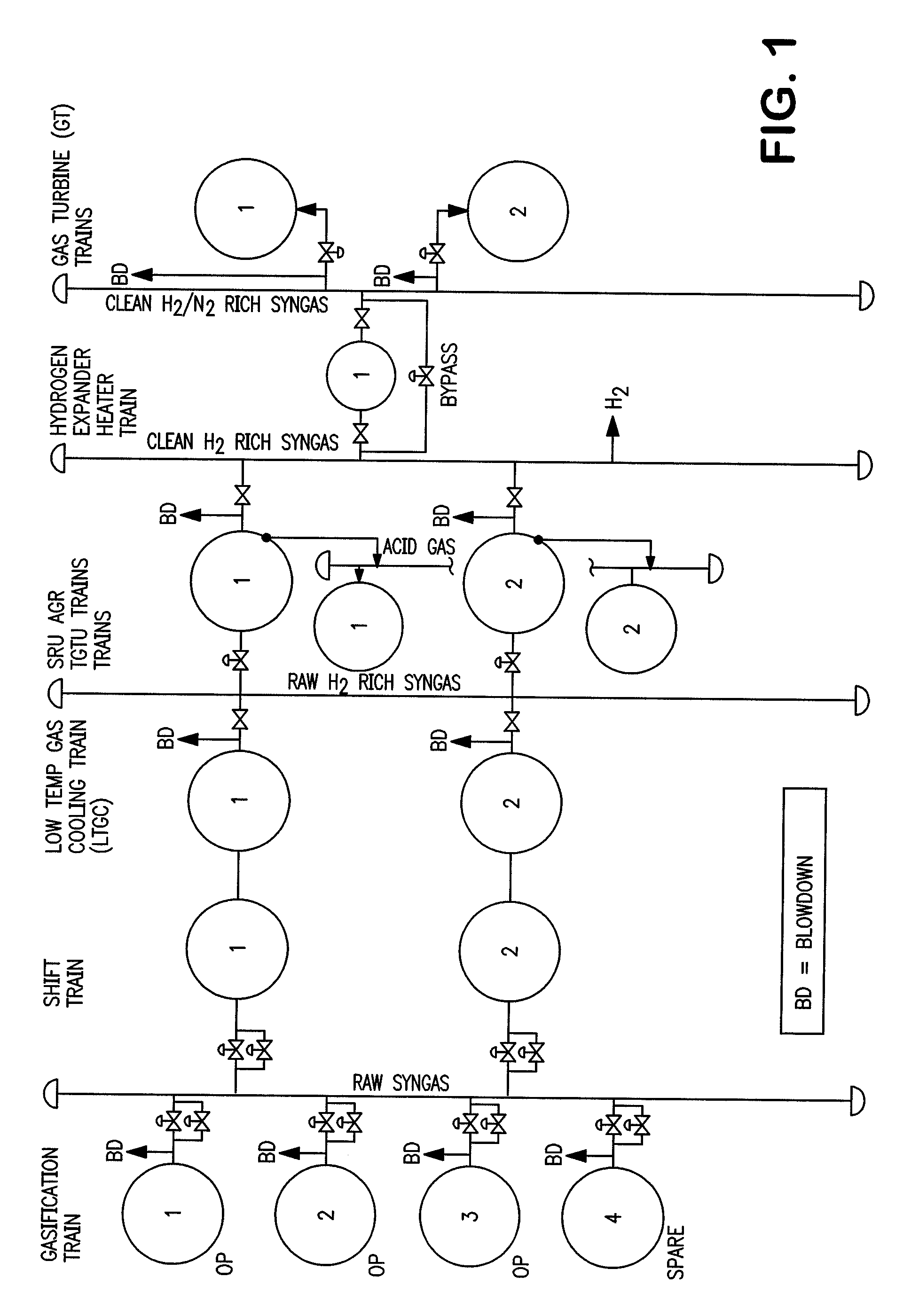
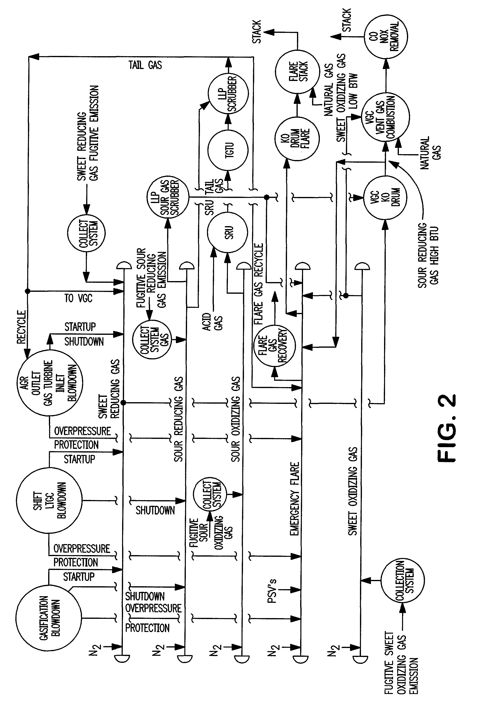
[0032]Broadly, in accordance with the present invention the syngas production zone or gasifier in an IGCC complex is started up with a clean, sulfur-free, containing less than about 10 ppmv sulfur hydrocarbon-containing feedstock such as natural gas or a light hydrocarbon liquid such as methanol. The sulfur-free syngas produced in the gasifier, a sweet reducing gas, is then sent to a vent gas combustor having a fuel nozzle for combustion via a blow down conduit downstream of the gasifier. When the downstream acid gas removal unit and the sulfur recovery unit and the tail gas treatment unit are commissioned, the clean fuel is switched to a high sulfur solid fuel. After the AGR is fully commissioned, the acid gas (H2S and other contaminants) are concentrated and sent to a sulfur recovery unit e.g. Claus unit to make elemental sulfur. If the acid gas concentration is less than 25% vol H2S in the acid gas during the start-up, such acid gas is routed to a sour gas scrubber. Once the SRU ...


PUM

PropertyMeasurementUnit
temperaturesaaaaaaaaaa
pressureaaaaaaaaaa

Abstract

Disclosed is a process to start-up, operate, and shut down a gasifier and an integrated gasification combined cycle complex without flaring while additionally reducing the release of contaminants such as carbon monoxide, hydrogen sulfide, and nitrogen oxides. The process is accomplished by scrubbing ventable sour gases and passing scrubbed sour gases and ventable sweet gases to a vent gas combustor for controlled combustion prior to release of any such gases to the atmosphere. Additionally, the gases are subjected to a CO oxidation treatment and selective catalytic reduction treatment prior to release to the atmosphere.

Description

BACKGROUND OF THE INVENTION[0001]The present invention relates to systems and methods of starting up, operating and shutting down a gasification reactor and an integrated gasification combined cycle (“IGCC”) complex.[0002]Gasification was first used to produce “town gas” for light and heat. Additionally, coal and other hydrocarbons have been gasified in the past to produce various chemicals and synthetic fuels. More recently gasification technology has been employed to generate electricity in an IGCC complex wherein coal or another hydrocarbon is gasified by partial oxidation using oxygen or air to syngas. Typically, this syngas is then cleaned of particulates, sulfur compounds and nitrogen compounds such as NOx compounds and then subsequently passed to gas turbine where it is fired. Additionally the hot exhaust gas from the gas turbine is usually passed to a heat recovery steam generator where steam is produced to drive a steam turbine. Electrical power is then produced from the ga...

Claims


Application Information

Patent Timeline
Patent Type & Authority Applications(United States)
IPC IPC(8): F02C3/28C10L3/08F01K23/06
CPCC01B3/34Y02E20/16C01B3/48C01B3/52C01B2203/02C01B2203/025C01B2203/0283C01B2203/0415C01B2203/0485C01B2203/1223C01B2203/1241C01B2203/1604C01B2203/1609C10J3/00C10J2300/0903C10J2300/093C10J2300/0943C10J2300/16C10J2300/1671C10J2300/1675F01K13/02F01K23/068F02C1/007F02C1/10F02C3/28F05D2270/082Y02E20/18C10K1/004C10K1/005C10K1/101C10K1/12C10K1/143C10J2300/1653C01B3/36
Inventor BALMAS, MARIACHAN, HENRY C.SKINNER, CRAIG
Owner HYDROGEN ENERGY INT
Why Eureka
Try Eureka